NT Camera: Difference between revisions
No edit summary |
|||
| (453 intermediate revisions by 4 users not shown) | |||
| Line 1: | Line 1: | ||
<span style="font-size:88%">''The information on this page refers to firmware v2.72e and higher.''</span> | |||
The NT | The NT Camera module allows us to remote control a camera. | ||
It thus serves a similar purpose as the various RC camera remote control modules, such as [http://vp-systems.eu/camremote.html CAMremote], [https://www.seagulluav.com/ Seagull], [https://www.gentles.ltd.uk/gentwire/multi.htm Gentles], [https://www.rcshutter.com/index.php?route=product/category&path=20 RcShutter], [http://wiki.mikrokopter.de/en/CamCtrl CamCntrl], [https://hobbyking.com/en_us/infrared-remote-shutter-controller-for-nikon-cameras.html IR Remote Shutter Controller], and all the other commercial and DIY solutions. | |||
However, instead of listening to e.g. a servo PWM signal, the NT Camera module listens to the data on the NT bus. It is thus usually connected to the NT bus near the camera NT Imu module, which results in extremely clean wiring schemes (see [[What is STorM32 NT about?|here]]). Separate NT Camera modules have in fact not emerged, but the NT Camera function is integrated into the NT Imu firmware. That is, the NT Imu module is also a NT Camera module (if it exposes the related pins to the user, which many of the available NT Imu modules do). For many camera models it is also possible to connect the camera, or a module operating it, directly to the STorM32 controller board, i.e., the STorM32 controller is then also a NT Camera module. | |||
In addition, the NT Camera module also serves as a "PWM Out" module. That is, it outputs a servo PWM signal, which is an exact mirror of the PWM output signal available on the main STorM32 board, when the {{PARAMNAME|Pwm Out Control}} parameter is enabled. This additional PWM signal can come in very handy and allows us doing all sorts of fancy things (e.g. motor zoom). It will not be further discussed in this article however. | |||
Historically, the STorM32's remote camera control started with an IR LED controller on the v1.3x main STorM32 board, and several camera models which were supported by the STorM32 were related to this, such as the Sony Nex. The NT Camera concept was introduced later, and extended to also provide PWM and serial UART signals to control cameras such as the Gitup Git2, RunCam Split, or GoPro Hero. The subsequent introduction of the [[MAVLink_Communication#MAVLink_Camera|MAVLink Camera component]] and the serial API has brought unprecedented cool camera control features to the user. | |||
<div class="toclimit-2">__TOC__</div> | <div class="toclimit-2">__TOC__</div> | ||
== NT Camera Support by NT | == Concept and Overview == | ||
=== Parameters === | |||
The NT Camera is related to a number of parameters, which are located in two places in the GUI, the {{GUI|Functions}} tab and the {{GUI|Interfaces Tool}} dialog. | |||
In the {{GUI|Functions}} tab we see: | |||
* {{PARAMNAME|Camera Control}}: Enables the function and selects the primary input. | |||
* {{PARAMNAME|Camera Control2}}: Selects a secondary input, which is used by some camera models. | |||
* {{PARAMNAME|Camera Model}}: Selects the camera model. | |||
* {{PARAMNAME|Camera Control Mode}}: Functions executed then the primary input value is High or Low. The default is {{PARAMVALUE|video - off - shutter}} (usually does not need to be changed). | |||
* {{PARAMNAME|Camera Time Interval}}: Setting this to 0 (off) will result in one photo being taken. If set to other than 0 photos will be taken continuously. The time period is from the start of the first photo to the start of the second photo, and so on. This parameter is functional for all camera models, and not further discussed below. | |||
* {{PARAMNAME|Camera ComPort}}: Selects the UART port for camera models which use a serial interface. | |||
In the {{GUI|Interfaces Tool}} dialog, accessible via the {{GUI|Experts Only}} menu, one finds further relevant parameters, which are associated with the [[MAVLink_Communication#MAVLink_Gimbal|MAVLink Gimbal]] and [[MAVLink_Communication#MAVLink_Camera|MAVLink Camera]] components: | |||
* {{PARAMNAME|Mavlink Gimbal}}: Enables the MAVLink Gimbal component and sets its component ID. | |||
* {{PARAMNAME|Mavlink ComPort}}: Selects the com port used for the MAVLink communication. | |||
* {{PARAMNAME|Mavlink System ID}}: Sets the system ID for both the MAVLink Gimbal and Camera components. A value of {{PARAMVALUE|0}} enables autodetection. | |||
* {{PARAMNAME|Mavlink Camera}}: Enables the MAVLink Camera component and sets its component ID. | |||
=== Camera Control Mode === | |||
The {{PARAMNAME|Camera Control Mode}} parameter determines if and when the shutter is released and the video is started or stopped. | |||
The setting {{PARAMVALUE|video - off - shutter}} means that the shutter is released when the primary input value switches from neutral to High, and that the video is started when it switches from neutral to Low and stopped when it switches from Low to neutral. The setting {{PARAMVALUE|shutter - off - video}} does the same, except that High and Low are swapped. | |||
The setting {{PARAMVALUE|off - shutter}} means that the shutter is released when the primary input value switches from neutral (or Low) to High, and that the video cannot be started or stopped. In contrast, {{PARAMVALUE|off - video}} means that the video is started when the primary input value switches from neutral (or Low) to High, and stopped when it switches from High to neutral (or Low), and that the shutter cannot be released. The settings {{PARAMVALUE|shutter - off}} and {{PARAMVALUE|video - off}} do the same, except that High and Low are swapped. | |||
=== Camera Connection === | |||
For some camera models the STorM32 checks if the camera is connected and up and running. Examples are the GoPro models since here not only a physical connection is needed but also a Wifi connection must be established, but this also applies to other models such as the {{PARAMVALUE|Runcam Split Mini2}}. | |||
For these models the GUI shows a "CAMERA" field in the {{GUI|Dashboard}} tab, with info such as "connected" or "not connected" which reveal the current state. | |||
{{COMMENT|The general rule is that if a bi-directional communication is involved, then the STorM32 checks connection for that camera model.}} | |||
=== Processing Scheme === | |||
The STorM32 camera remote control is based on three elementary operations: SHUTTER, VIDEOON and VIDEOOFF. These are supported by all camera models, and can be triggered by various sources: a signal on any of the STorM32's inputs, a script, a serial command, a MAVLink message to the MAVLink Gimbal component, or a MAVLink message to the MAVLink Camera component. The NT Camera module translates these elementary operations into the corresponding output signals as required for the specified camera model. The output signals can be PWM, low-high-low pulses, UART Tx and Rx, or whatever is required. | |||
In addition, some camera models (such as the {{PARAMVALUE|Runcam Split Mini2}} and {{PARAMVALUE|GoPro Hero7}}) provide a much richer set of features and functions, which the STorM32 makes accessible to the user via the [https://mavlink.io/en/services/camera.html MAVLink Camera Protocol microservice] provided by the MAVLink Camera component. This "richer set of features and functions" is in fact most cool and not easily explained in one sentence. It for instance allows the user to access many if not all camera settings from ground control stations such as QGroundControl, like it is known for DJI drones or the 3DR Solo. | |||
:[[File:Storm32-nt-ntcamera-processing.jpg|none|680px|center]] | |||
== NT Camera Support by NT Imu Modules == | |||
As mentioned in the introduction, the NT Camera is integrated into the NT Imu firmware. The NT Imu module provides these three signals on its EXT port pins: | |||
* EXT-3: Camera PWM signal, or Uart Tx, or other | |||
* EXT-2: Camera pulse signal, or Uart Rx, or other | |||
* EXT-1: Pwm Out servo PWM signal (with ca. 60 Hz frequency) | |||
The "Pwm Out" signal on pin EXT-1 is related to the {{PARAMNAME|Pwm Out Control}} function and is not further discussed here. See [[Advanced_Functions#Pwm_Out|Advanced Functions: Pwm Out]]. | |||
The "Camera" signals on EXT-3 and EXT-2 are related to the {{PARAMNAME|Camera Control}} and {{PARAMNAME|Camera Control2}} functions, and depend on the {{PARAMNAME|Camera Model}} setting. For many camera models they are configured to output a PWM servo signal on EXT-3 and a pulse signal on EXT-2: | |||
* The PWM signal can directly feed cameras which can be triggered by such signals, such as the Gitup Git2, or can be connected to common RC camera remote control modules, such as those mentioned in the introduction. The frequency of the PWM signal is ca. 60 Hz. | |||
* The pulse signal consists of a 50 ms low/high/low pulse and can be used for all sorts of purposes. For instance, it could be connected to a [http://www.rcgroups.com/forums/showpost.php?p=30034371&postcount=2437 semiconductor relais] to drive an IR LED or shorten some pins on a USB remote. | |||
The EXT-3 and EXT-2 pins can also assume other functions however. For instance, for GoPro cameras they are configured to operate as Tx and Rx UART signals. | |||
The function matrix looks as this: | |||
{| class="wikitable" | |||
!camera model | |||
!EXT-3 | |||
!EXT-2 | |||
|- | |||
| Generic Rc, Git2 Rc, Mapir Survey Rc || PWM || pulse | |||
|- | |||
| CAMremote Rc || PWM || PWM2 passthrough (*) | |||
|- | |||
| Firefly Split 4K Rc || pulse || pulse | |||
|- | |||
| Pwm || PWM passthrough || PWM2 passthrough (*) | |||
|- | |||
| Runcam Generic || Tx || pulse (*) | |||
|- | |||
| CAMremote UART,</br>Visca || Tx || pulse (*) | |||
|- | |||
| GoPro Hero7, GoPro Hero5, GoPro Generic,</br> Serial Api || Tx || Rx | |||
|} | |||
=== Pin Assignment on the v1.x, v2.x, and v4.x NT Imu Modules === | |||
------ | |||
The v4.x, v2.x, and the "big" v1.x NT Imu modules expose the additional EXT port pins: | |||
:[[File:Storm32-nt-imu-v42-docu.jpg|460px]] [[File:Storm32-nt-imu-v21-docu.jpg|460px]] | |||
::[[File:Storm32-nt-imu-v10-docu-02.jpg|360px]] | |||
=== Pin Assignment for the CC3D Atom and Atom Mini === | |||
------ | |||
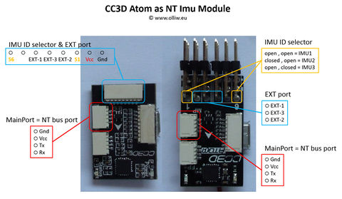
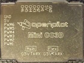
Both the CC3D Atom and Atom Mini have six servo outputs labeled PWM1 to PWM6. They are assigned as follows to the EXT port pins: | |||
* PWM2 = EXT-1 = Pwm Out servo PWM signal | |||
* PWM3 = EXT-3 = Camera servo PWM signal | |||
* PWM4 = EXT-2 = Camera pulse signal | |||
:[[File:Storm32-nt-imu-cc3datom-docu-03.jpg|480px]] [[File:CC3D_Case_Label.jpg|280px]] | |||
== RunCam == | |||
The NT Camera can control a RunCam Split Mini2 by communicating to it via the camera's serial port. It has been confirmed to work also for a RunCam Split 2S and a RunCam Split Micro V3. It probably works for other similar cameras, but this is untested. | |||
Set these parameters in the {{GUI|Functions}} tab: | |||
* {{PARAMNAME|Camera Control}}: Set to the desired input to trigger photos or start/stop videos. Can be {{PARAMVALUE|off}} if MAVLink is used only. | |||
* {{PARAMNAME|Camera Model}} = {{PARAMVALUE|Runcam Generic}} | |||
* {{PARAMNAME|Camera ComPort}} = Set to {{PARAMVALUE|default}} if the camera is connected to the NT Imu module, or chose the UART, UART2 or UARTX port. | |||
If you also want the MAVLink Camera features, then in addition set these parameters in the {{GUI|Interfaces}} menu: | |||
* {{PARAMNAME|Mavlink Camera}} = {{PARAMVALUE|Camera1}} or higher | |||
* {{PARAMNAME|Mavlink System ID}}: usually can be {{PARAMVALUE|0}} | |||
{{COMMENT|Some RunCam cameras such as the RunCam Split 2S provide video and photo modes. The RunCam protocol however does not allow us to reliably switch between video and photo mode, and the STorM32 therefore only supports the video mode. The implication is that the camera must be in video mode at startup.}} | |||
=== Camera Models === | |||
The {{PARAMVALUE|Runcam Generic}} model allows us to start and stop recording a video. The underlying UART commands should be supported by all RunCam models with UART interface, so that this model is expected to work for them all. | |||
=== Wiring === | |||
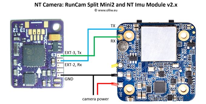
The | The connection diagram for a NT Imu v2.x looks like this: | ||
:[[File:Storm32-nt-ntcamera-runcamsplitmini2.jpg|none|680px|center]]<!-- | |||
The | The NT Camera can control a RunCam Split Mini2 by communicating to it via the camera's serial port. It has been confirmed to work also for a RunCam Split 2S and a RunCam Split Micro V3. It probably works for other similar cameras, but this is untested. | ||
{{#ev:youtube|nGszTJCzSMk|480}} | |||
:[[File:Storm32-nt- | Set these parameters in the {{GUI|Functions}} tab: | ||
* {{PARAMNAME|Camera Control}}: Set to the desired input to trigger photos or start/stop videos. Can also be {{PARAMVALUE|off}}. | |||
* {{PARAMNAME|Camera Control2}}: Set to the desired input to access OSD. Can also be {{PARAMVALUE|off}}. | |||
* {{PARAMNAME|Camera Model}} = {{PARAMVALUE|Runcam Generic}} or {{PARAMVALUE|Runcam Split Mini2}} | |||
* {{PARAMNAME|Camera ComPort}} = {{PARAMVALUE|default}} | |||
If you also want the MAVLink Camera features, then in addition set these parameters in the {{GUI|Interfaces}} menu: | |||
* {{PARAMNAME|Mavlink Camera}} = {{PARAMVALUE|Camera1}} or higher | |||
* {{PARAMNAME|Mavlink System ID}}: usually can be {{PARAMVALUE|0}} | |||
{{COMMENT|Some RunCam cameras such as the RunCam Split 2S provide video and photo modes. The RunCam protocol however does not allow us to reliably switch between video and photo mode, and the STorM32 therefore only supports the video mode. The implication is that the camera must be in video mode at startup.}} | |||
=== Camera Models === | |||
Currently two camera models are available, {{PARAMVALUE|Runcam Generic}} and {{PARAMVALUE|Runcam Split Mini2}}. | |||
The {{PARAMVALUE|Runcam Generic}} model allows us to start and stop recording a video. The underlying UART commands should be supported by all RunCam models with UART interface, so that this model is expected to work for them all. | |||
=== Wiring === | |||
The connection diagram for a NT Imu v2.x looks like this (works similarly for the other NT Imu modules): | |||
:[[File:Storm32-nt-ntcamera-runcamsplitmini2.jpg|none|680px|center]] | |||
--> | |||
== GoPro Hero == | |||
The NT Camera can control a GoPro camera by communicating with it via Wifi. | |||
{| | |||
|width=370|{{#ev:youtube|kT4zbvChs2g|420}} | |||
|{{#ev:youtube|rhzkxKO-40c|420}} | |||
|} | |||
Here one thus requires an additional Wifi module, such as an ESP8266, Arduino MKR1000, or ESP32. The MKR1000 is quite pricey and very large, the ESP8266 works a bit dodgy, so I currently use a ESP32, which to me is the best deal. The Wifi module needs to be loaded with a particular firmware, and an Arduino sketch is available in my github repo (see link below)(currently only the ESP32 is supported, but you are of course welcome to adapt the sketch to also support e.g. the ESP8266). | |||
If you want to know more details about the technical inside, you may read [https://www.rcgroups.com/forums/showpost.php?p=42481889&postcount=2295 this post]. | |||
The Arduino sketches and C files (and other relevant material) are open source (GLP-v3) and available here: https://github.com/olliw42/goprohero. | |||
''{{WARNING|WARNING: Both Wifi and most radio control systems work in the 2.4 GHz range, and interferences may thus happen and compromise your remote control signal quality}}''. Unfortunately I could not find a single competent report or analysis of this topic on the web; all reports I found which say that it works are based on purely anecdotal evidence. So, please, be warned! In order to avoid issues as much as possible I have at least set the Wifi module's transmit power to the lowest possible level. | |||
The Wifi module (loaded with the Arduino sketch) is connected via its serial port to the NT Camera module, i.e. the EXT-3 and EXT-2 pins on your NT Imu module (see [[NT_Camera#NT_Camera_Support_by_NT_Imu_Modules | NT Camera Support by NT Imu Modules]]). Alternatively, the Wifi module can be connected to the UART or UART2 port on the main STorM32 controller, which often can be the more convenient setup, as it much simplifies wiring. | |||
{{COMMENT|Wifi modules generally need to be powered from a strong, stable power source, since current draw can be high (not on average, but in the spikes). So, do not use the NT bus 5 V power line, unless you have ensured that it is of sufficient high power or understand what you're doing.}} | |||
Set these parameters in the {{GUI|Functions}} tab: | |||
* {{PARAMNAME|Camera Control}}: Set to the desired input to trigger photos or start/stop videos. Can be {{PARAMVALUE|off}} if MAVLink is used only. | |||
* {{PARAMNAME|Camera Model}} = {{PARAMVALUE|GoPro Hero7}}, {{PARAMVALUE|GoPro Hero5}} or {{PARAMVALUE|GoPro Generic}} | |||
* {{PARAMNAME|Camera ComPort}}: Set to {{PARAMVALUE|default}} if the Wifi module is connected to the NT Imu module, or chose the UART, UART2 or UARTX port. | |||
If you also want the MAVLink Camera features, then in addition set these parameters in the {{GUI|Interfaces}} menu: | |||
* {{PARAMNAME|Mavlink Camera}} = {{PARAMVALUE|Camera1}} or higher | |||
* {{PARAMNAME|Mavlink System ID}}: usually can be {{PARAMVALUE|0}} | |||
=== Camera Models === | |||
Currently three GoPro camera models are available, {{PARAMVALUE|GoPro Hero7}}, {{PARAMVALUE|GoPro Hero5}} and {{PARAMVALUE|GoPro Generic}}. However, other GoPro cameras probably will work too. | |||
The {{PARAMVALUE|GoPro Generic}} model only provides basic support, i.e., only allows us to start and stop recording a video and taking pictures. It does so by using a Wifi command which is expected to be supported by '''''all''''' GoPro models with a Wifi interface. Accordingly, this model should work for all GoPro cameras. | |||
The other camera models use Wifi settings which can be specific to the particular model, and if a model works also for other GoPro cameras thus depends on the compatibility details. | |||
=== Huzzah32-ESP32 Breakout Board === | |||
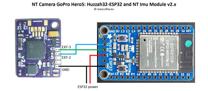
The connection diagram for a NT Imu v2.x and an [https://www.adafruit.com/product/4172 Adafruit HUZZAH32–ESP32 Breakout Board] can look as this: | |||
:[[File:Storm32-nt-ntcamera-huzzah-esp32.jpg|none|680px|center]] | |||
{{COMMENT|The HUZZAH32–ESP32 breakout board was the best option I found price and size wise, and that's why I use it. The connection diagram should be similar for other ESP32 boards.}}<!--{{COMMENT|The HUZZAH32–ESP32 breakout board was the best option I found price and size wise. It's a cute board, with however a nasty flaw: see [[https://forums.adafruit.com/viewtopic.php?f=57&t=153553 here]], where also solutions are provided.}}--> | |||
== CAMremote == | |||
The CAMremote from VP-Systems is a highly functional and versatile camera remote controller. The STorM32 supports it by two camera models, called {{PARAMVALUE|CAMremote Rc}} and {{PARAMVALUE|CAMremote UART}}. | |||
=== CAMremote RC === | |||
The CAMremote provides several settings where the shutter and video on/off can be controlled via a PWM signal on the CAMremote's CH0 input. In combination with the NT Camera module, several configurations are possible, the most generic one would be to use either of these: | |||
* CH0 = Record/AF/Shoot | |||
* CH0 = Record/Shoot | |||
The EXT-3 pin on the NT Imu module should then be connected to the CH0 input on the CAMremote. | |||
The PWM2 passthrough output on the NT Imu module, or pin EXT-2, can then be connected to the CAMremote's CH1 to invoke additional features, such a manual focus, zoom in/out, and so on. | |||
'''''Comment''': This has been tested using NT Imu firmware v0.28 and "RC receiver (CH0=Record/AF/Shoot, CH1=SmoothZoom, CH2=Alt)-mode" on CAMremote 3.0.9. In case the shutter does not trigger a photo on the camera it might be necessary to increase the focus time to give the camera time to focus.'' | |||
The disadvantage of using the CAMremote with PWM input signals is that one only can toggle between VIDEOON and VIDEOOFF, and not directly set VIDEOON or VIDEOOFF, so that the actual recording state might be lost by the user. | |||
=== CAMremote UART === | |||
The CAMremote also provides a serial UART interface, which provides access to a much richer set of features and functions than with the control via PWM signals. | |||
The EXT-3 and EXT-2 pins on the NT Imu module should be connected to the Tx/Rx inputs on the CAMremote, respectively. | |||
Currently, the STorM32 supports the 'shoot', 'recon' and 'recoff' commands. | |||
This brings the great advantage that VIDEOON and VIDEOOFF are now set directly, and not only toggled as with the PWM input, so that the actual recording state is always known to the user. | |||
=== Links === | |||
* http://vp-systems.eu/camremote.html | |||
* http://vp-systems.eu/manual_cr.html | |||
* https://vp-systems.eu/cr_uart.html | |||
== Visca PTZ == | |||
The NT Camera supports PTZ cameras using the VISCA protocol. | |||
The EXT-3 pin on the NT Imu module should be connected to the Rx input on the PTZ camera (not RS232 or RS422, but UART-TTL input). The baud rate is 9600 baud. In addition, if configured in the GUI, the signal is available on a UART port on the STorM32 contoller with 115200 baud. | |||
Set these parameters in the {{GUI|Functions}} tab: | |||
* {{PARAMNAME|Camera Control}}: Set to the desired input to trigger power on/off. Can be {{PARAMVALUE|off}} if only MAVLink is used. | |||
* {{PARAMNAME|Camera Control2}}: Set to the desired input to zoom in or out. Can be {{PARAMVALUE|off}} if not needed. | |||
* {{PARAMNAME|Camera Model}} = {{PARAMVALUE|Visca}} | |||
* {{PARAMNAME|Camera ComPort}} = Set to {{PARAMVALUE|default}} if the camera is connected to the NT Imu module, or chose the UART, UART2 or UARTX port. | |||
STorM32 supports VISCA commnds to start and stop video recording, and handle zoom and focus. The VISCA commands can be issued via inputs or MAVLink commands. | |||
The VISCA commands (supported by STorM32) have the structure | |||
0x81 0x01 0x04 cmd-bytes 0xFF | |||
where cmd-bytes are multiple bytes determining the task to execute. These commands are supported (only cmd-bytes are given): | |||
0x00 0x02: video on (CAM_Power On) | |||
0x00 0x03: video off (CAM_Power Off) | |||
0x07 0x2p: zoom tele (CAM_Zoom Tele Variable Speed, p can be 0 ..7) | |||
0x07 0x00: zoom stop (CAM_Zoom Stop) | |||
0x07 0x3p: zoom wide (CAM_Zoom Wide Variable Speed, p can be 0 ..7) | |||
0x47 0x0p 0x0q 0x0r 0x0s: zoom direct (CAM_Zoom Direct, 0xpqrs can be in range 0x0000...0x4000) | |||
0x08 0x2p: focus far (CAM_Focus Far Variable Speed, p can be 0 ..7) | |||
0x08 0x00: focus stop (CAM_Focus Stop) | |||
0x08 0x3p: focus near (CAM_Focus Near Variable Speed, p can be 0 ..7) | |||
0x48 0x0p 0x0q 0x0r 0x0s: focus direct (CAM_Focus Direct, 0xpqrs can be in range 0x0000...0xFFFF) | |||
0x38 0x03: focus manual mode (CAM_Focus Manual Focus) | |||
0x38 0x02: focus AF mode (CAM_Focus Auto Focus) | |||
0x18 0x01: focus AF single (CAM_Focus One Push Trigger) | |||
The power on/off VISCA commands are mapped to the video on/off function, available with the {{PARAMNAME|Camera Control}} input. The zoom tele/stop/wide VISCA commands are attached to the {{PARAMNAME|Camera Control2}} input. | |||
The full set of supported VISCA commands are available via MAVLink commands MAV_CMD_DO_DIGICAM_CONFIGURE, MAV_CMD_DO_DIGICAM_CONTROL, MAV_CMD_DO_SET_CAM_TRIGG_DIST, MAV_CMD_SET_CAMERA_MODE, MAV_CMD_SET_CAMERA_ZOOM, MAV_CMD_SET_CAMERA_FOCUS, MAV_CMD_VIDEO_START_CAPTURE, MAV_CMD_VIDEO_STOP_CAPTURE. | |||
{{COMMENT|VISCA cameras implement the VISCA protocol in different ways and the above commands may or may not work for your camera.}} | |||
=== Links === | |||
* https://www.epiphan.com/userguides/LUMiO12x/Content/UserGuides/PTZ/3-operation/VISCAcommands.htm | |||
* https://www.snapav.com/wcsstore/ExtendedSitesCatalogAssetStore/attachments/documents/USBProducts/ManualsAndGuides/Visca%20Protocol2.pdf | |||
== Firefly Split 4K == | |||
The Firefly Split 4K can be controlled by two HIGH-LOW-HIGH pulses for triggering shutter and starting/stopping video recording. | |||
The EXT-3 and EXT-2 port pins on the NT Imu module are assigned as follows: | |||
* EXT-3: HIGH-LOW-HIGH pulse of 100 ms duration for shutter control | |||
* EXT-2: HIGH-LOW-HIGH pulse of 100 ms duration for starting/stoping video recording | |||
In the {{GUI|Functions}} tab set as follows: | |||
* {{PARAMNAME|Camera Control}} = {{PARAMVALUE|Rc-0}}, or whatever input port you wish to use | |||
* {{PARAMNAME|Camera Model}} = {{PARAMVALUE|Firefly Split 4K Rc}} | |||
The parameters {{PARAMNAME|Camera Control2}} and {{PARAMNAME|Camera ComPort}} are irrelevant, and the remaining parameters have their usual meaning. | |||
The Firefly Split 4K can crash when the trigger inputs are too fast (especially when starting/stopping video, tested with firmware 20201015); the STorM32 controller thus enforces a delay of 4 seconds between the trigger pulses to prevent this. | |||
=== Wiring === | |||
Connect the trigger input pins of the Firefly 4K Split camera as follows to the pins on the NT [[Pins_and_Connectors_of_NT_Modules|Imu]] module: | |||
* green cable, rightmost pin: connect to EXT-2 | |||
* blue cable: connect to EXT-3 | |||
The PCB of the camera is conformal coated. If you want to solder directly to its connector pins, you first should remove the coating with a glass fiber pencil. | |||
The camera board provides 3.3 V on solder pads next to the connector and 5 V on a capacitor pin (see Hawkeye's official web page linked to below). This can be used to power the NT Imu module and save one wire. Both the 3.3 V and 5 V sources work, but the 5 V is preferred. | |||
As the NT Imu module is working with 3.3 V and thus outputs maximal 3.3 V, you can disregard the manual's warning to not connect any power to the trigger pins. | |||
=== Links === | |||
* Official "How to connect Hawkeye Firefly 4K Split Cam" information: http://www.cnfpv.com/portal.php?mod=view&aid=158 | |||
== Gitup Git2 == | == Gitup Git2 == | ||
The Gitup Git2 can receive a PWM signal on its Micro HDMI port to control video recording and photo triggering. The details can be found on the Gitup site. In general, a 3 position switch will be used on your transmitter: The middle position should be set to 1500 µs and will do nothing. Low position, < 1250 µs, will start recording video when switched. High position, > 1800 µs, will take a photo when switched. If your transmitter channel is setup as 0%, 50%, 100% (or -100, 0, 100) for Low, Mid, and High, then you should be fine. | |||
{{COMMENT|To avoid misunderstanding, please note that the transmitter switch PWM values mentioned for transmitter setup are not those which are send to the camera. The STorM32 will translate the received input PWM values into those required by the camera.}} | |||
Links: | Links: | ||
* http://www.rcgroups.com/forums/showpost.php?p=34538383&postcount=3443 | * http://www.rcgroups.com/forums/showpost.php?p=34538383&postcount=3443 | ||
* https://www.gitup.com/cameras/73-gitup-git2p-standard-packing-170-degree-lens.html | |||
=== Cable Information === | === Cable Information === | ||
Gitup | Gitup provides a Remote Shutter cable. If you choose to make your own, then please follow the pinouts for the [https://en.wikipedia.org/wiki/HDMI#Connectors Micro HDMI (type D)] connector, not Mini or full size because they are different (see [https://upload.wikimedia.org/wikipedia/commons/a/a5/HDMI_Connector.jpg here]). | ||
* Signal In: Micro HDMI Pin 2 (usually denoted as Utility or Reserved on pinouts) | |||
* Signal Gnd: Micro HDMI Pin 4 (TMDS Data2 Shield, or any other shield pin; even the connector's case works) | |||
:[[File:Git2 Micro HDMI Pinout.jpg|360px]] | |||
{{COMMENT|The Git2 uses its Mini USB port for both Video Out and Power In to charge or power the camera. While Gitup also provides this cable, FPV cables for the GoPro works as well. Gitup also provides a combo board/cable, which contains both the HDMI and USB connectors.}} | |||
=== Cable and Camera Function Test === | === Cable and Camera Function Test === | ||
Once you have your cable and transmitter configured as above connect your receiver | Once you have your cable and transmitter configured as above, connect your receiver or flight controller, and test it out. It should work before moving to the next step. | ||
=== CC3D NT Imu, STorM32 and Git2 Camera Integration === | |||
This section is based on using the Mini CC3D Atom. Other NT Imu modules which expose the EXT pins should work equally well however. The following is only one of the several possible configuration options available with the STorM32. | |||
{{COMMENT| Your STorM32 and NT Imu module need to communicate correctly, it is however not mandatory that the gimbal has been configured or tuned.}} | |||
Wire up as follows: | |||
* Connect your receiver, or flight controller, to one of the seven STorM32 RC ports (RC-0 through RC2-3), or use any other input channel (see [[Inputs and Functions]]). | |||
* Connect the Git2 Remote Shutter cable to the EXT-3 and GND pins on the NT Imu module (see [[NT_Camera#NT_Camera Support_by_NT_Imu_Modules|NT Camera Support by NT Imu Modules]]). | |||
* | In the {{GUI|Functions}} tab use the column for {{PARAMNAME|Camera Control}} and set as follows: | ||
* {{PARAMNAME|Camera Control}} = {{PARAMVALUE|Rc-0}}, or whatever input port you wish to use | |||
* {{PARAMNAME|Camera Model}} = {{PARAMVALUE|Git2 Rc}} | |||
The parameters {{PARAMNAME|Camera Control2}} and {{PARAMNAME|Camera ComPort}} are irrelevant, and the remaining parameters have their usual meaning. | |||
== Foxeer Legend 1 == | == Foxeer Legend 1 == | ||
This should work as for the Gitup Git2, with identical settings. This has not yet been tested though. | |||
* http://foxeer.com/XAT800-Effio-V-Camera-a-10.html | * http://foxeer.com/XAT800-Effio-V-Camera-a-10.html | ||
* http://data.foxeer.com/Manual_LEGEND1_FOXEER.pdf | * http://data.foxeer.com/Manual_LEGEND1_FOXEER.pdf | ||
== | == Mapir Survey == | ||
The Mapir Survey is in many regards similar to the Gitup Git2. For instance, it also can receive a PWM signal on its Micro HDMI port for control. However, the PWM signal required by the Mapir is quite different to that for the Git2. Furthermore, only photos can be triggered, but video recording cannot be started/stopped. Thus, the Git2 camera model cannot be used for the Mapir. | |||
The electrical connections and setup are largely identical to the Git2, so please look up there. These differences might be noteworthy: | |||
In general, a 2 position switch will be used on your transmitter: The middle position should be set to 1500 µs and will do nothing. High position, > 1800 µs, will take a photo when switched. | |||
In the {{GUI|Functions}} tab use the column for {{PARAMNAME|Camera Control}} and set as follows: | |||
* {{PARAMNAME|Camera Control}} = {{PARAMVALUE|Rc-0}}, or whatever input port you desire | |||
* {{PARAMNAME|Camera Model}} = {{PARAMVALUE|Mapir Survey Rc}} | |||
The parameters {{PARAMNAME|Camera Control2}} and {{PARAMNAME|Camera ComPort}} are irrelevant, and the remaining parameters have their usual meaning. | |||
{{COMMENT|To avoid misunderstanding, please note that the transmitter switch PWM values mentioned for transmitter setup are not those which are send to the camera. The STorM32 will translate the received input PWM values into those required by the camera.}} | |||
=== Links === | |||
* https://www.rcgroups.com/forums/showthread.php?2055844-STorM32-BGC-32-bit-3-axis-brushless-gimbal-controller/page232&perpage=50#post42713367 | |||
* https://www.mapir.camera/pages/survey3-cameras | |||
* https://cdn.shopify.com/s/files/1/0878/4732/files/MAPIR_Survey3_Manual_v1.pdf | |||
== Serial API == | |||
The {{PARAMVALUE|Serial Api}} is a special camera model, designed to inter-operate with an external computing device, such as a Raspberry Pi, Arduino, and alike, via a serial data line (in the following the example of a Raspberry Pi, denoted as RPi, is chosen). The prototypical application example would be to integrate [http://www.gphoto.org/ gphoto]-controlled cameras into the STorM32 system. | |||
The RPi is connected to the UART on the STorM32 controller which is selected in the parameter {{PARAMNAME|Camera ComPort}}. The serial API camera model then provides a set of commands to exchange information between the STorM32's NT Camera functionality and the RPi. On the RPi a script is running which handles the communication, i.e., translates the commands of the serial API into the corresponding actions needed for the specific camera which shall be operated, and vice versa. | |||
In the {{GUI|Functions}} tab set as follows: | |||
* {{PARAMNAME|Camera Model}} = {{PARAMVALUE|Serial Api}} | |||
* {{PARAMNAME|Camera ComPort}}: Select the UART ({{PARAMVALUE|default}} is currently not supported) | |||
The serial API currently consists of the following: | |||
* "shutter\n", "videoon\n", "videooff\n": These commands correspond to the STorM32's internal SHUTTER, VIDEOON and VIDEOOFF states, and are send whenever the respective state is assumed. This can be via an input as selected in the parameter {{PARAMNAME|Camera Control}}, a serial command, a MAVLink command, or via the MAVLink Camera microservice. | |||
* "cntrl2high\n", "cntrl2low\n", "cntrl2stop\n": These commands are send according to the state of the input selected in the parameter {{PARAMNAME|Camera Control2}}. | |||
* SENDCAMTEXT: This [[STorM32_Scripts|script]] command sends a user-defined string to the RPi (the string is appended by a '\n' character). This allows us to use the potential of scripts for controlling the camera handled by the RPi. | |||
An example Python script which can be run on a RPi is available in the firmware .zip file. | |||
== UartX Configuration == | |||
The number of available UART ports on STorM32 boards is limited, especially on v1.3 boards, and it can thus happen that one is running out of them. | |||
In such cases, the RC-0 and RC-1 input pins can be reconfigured to work as a further UART port, then named UARTX. This comes at the obvious cost that these inputs cannot be used anymore as PWM, Spektrum, SBus, and alike inputs. | |||
For this, set: | |||
* {{PARAMNAME|UartX Configuration}} = {{PARAMVALUE|uartX @ 115200}} (the parameter is located in the {{GUI|Setup}} tab) | |||
* {{PARAMNAME|Camera ComPort}} = {{PARAMVALUE|uartX}} | |||
The physical assignment is | |||
* RC-0 = UARTX Rx | |||
* RC-1 = UARTX Tx | |||
For the location of the RC-0, RC-1 pins on your board please refer to [[Pins and Connectors]]. | |||
== Stand-alone Use == | |||
The NT Camera can also be used stand-alone, without a gimbal. This effectively allows us to convert any of the supported cameras into a MAVLink camera. | |||
This mode of operation can be especially useful for those camera models which provide features beyond the basic SHUTTER, VIDEOON, and VIDEOFF operations, such as the Runcam Split Mini2 or the GoPro Hero models. | |||
The camera and MAVLink settings are as described in the above for the respective camera model. Typically, the UART port would be used for the MAVLink connection to a flight controller, and the UART2 port for connecting to the camera. | |||
The main difference in setup would be to also disable the motors, by setting in the {{GUI|Setup}} tab: | |||
* {{PARAMNAME|Pitch Motor Usage}} = {{PARAMVALUE|disabled}} | |||
* {{PARAMNAME|Roll Motor Usage}} = {{PARAMVALUE|disabled}} | |||
* {{PARAMNAME|Yaw Motor Usage}} = {{PARAMVALUE|disabled}} | |||
=== Wiring === | |||
For a v3.x STorM32 board the connection scheme could be as this, here shown for the example of the GoPro Hero model: | |||
:[[File:Storm32-nt-ntcamera-standalone-goprohero.jpg|680px]] | |||
For a v1.x STorM32 board the UARTX configuration capability can come in handy. The setup for a Runcam Split Mini2could look like this: | |||
:[[File:Storm32-nt-ntcamera-standalone-runcamsplitmini2-v13board.jpg|680px]] | |||
=== Links === | |||
* https://www.rcgroups.com/forums/showthread.php?3422673-Mavlink-Camera-Conversions-%28using-STorM32%29 | |||
== | == IR Led Support == | ||
IR Leds are not natively supported. It is possible though to use any of the RC camera remote controller (some were listed on the top of the page). You also can make use of the pulse signal on (some of) the NT Imu modules or STorM32 boards and connect it to a [http://www.rcgroups.com/forums/showpost.php?p=30034371&postcount=2437 semiconductor relais] to drive a IR Led. It is also easy to build your own IR controller e.g. using an Arduino, which then even can be made easily to use a serial camera model. | |||
{{COMMENT|STorM32 v1.x boards have a dedicated IR Led driver on board, which in earlier firmware versions could be used to control cameras like the Sony Nex by IR remote. With version v2.61h IR Led support has been removed.}} | |||
== Code Examples == | |||
Please see [[Code_Examples#NT_Camera|Code Examples: NT Camera]]. | |||
Latest revision as of 21:55, 14 June 2025
The information on this page refers to firmware v2.72e and higher.
The NT Camera module allows us to remote control a camera.
It thus serves a similar purpose as the various RC camera remote control modules, such as CAMremote, Seagull, Gentles, RcShutter, CamCntrl, IR Remote Shutter Controller, and all the other commercial and DIY solutions.
However, instead of listening to e.g. a servo PWM signal, the NT Camera module listens to the data on the NT bus. It is thus usually connected to the NT bus near the camera NT Imu module, which results in extremely clean wiring schemes (see here). Separate NT Camera modules have in fact not emerged, but the NT Camera function is integrated into the NT Imu firmware. That is, the NT Imu module is also a NT Camera module (if it exposes the related pins to the user, which many of the available NT Imu modules do). For many camera models it is also possible to connect the camera, or a module operating it, directly to the STorM32 controller board, i.e., the STorM32 controller is then also a NT Camera module.
In addition, the NT Camera module also serves as a "PWM Out" module. That is, it outputs a servo PWM signal, which is an exact mirror of the PWM output signal available on the main STorM32 board, when the Pwm Out Control parameter is enabled. This additional PWM signal can come in very handy and allows us doing all sorts of fancy things (e.g. motor zoom). It will not be further discussed in this article however.
Historically, the STorM32's remote camera control started with an IR LED controller on the v1.3x main STorM32 board, and several camera models which were supported by the STorM32 were related to this, such as the Sony Nex. The NT Camera concept was introduced later, and extended to also provide PWM and serial UART signals to control cameras such as the Gitup Git2, RunCam Split, or GoPro Hero. The subsequent introduction of the MAVLink Camera component and the serial API has brought unprecedented cool camera control features to the user.
Concept and Overview
Parameters
The NT Camera is related to a number of parameters, which are located in two places in the GUI, the [GUI:Functions] tab and the [GUI:Interfaces Tool] dialog.
In the [GUI:Functions] tab we see:
- Camera Control: Enables the function and selects the primary input.
- Camera Control2: Selects a secondary input, which is used by some camera models.
- Camera Model: Selects the camera model.
- Camera Control Mode: Functions executed then the primary input value is High or Low. The default is “video - off - shutter” (usually does not need to be changed).
- Camera Time Interval: Setting this to 0 (off) will result in one photo being taken. If set to other than 0 photos will be taken continuously. The time period is from the start of the first photo to the start of the second photo, and so on. This parameter is functional for all camera models, and not further discussed below.
- Camera ComPort: Selects the UART port for camera models which use a serial interface.
In the [GUI:Interfaces Tool] dialog, accessible via the [GUI:Experts Only] menu, one finds further relevant parameters, which are associated with the MAVLink Gimbal and MAVLink Camera components:
- Mavlink Gimbal: Enables the MAVLink Gimbal component and sets its component ID.
- Mavlink ComPort: Selects the com port used for the MAVLink communication.
- Mavlink System ID: Sets the system ID for both the MAVLink Gimbal and Camera components. A value of “0” enables autodetection.
- Mavlink Camera: Enables the MAVLink Camera component and sets its component ID.
Camera Control Mode
The Camera Control Mode parameter determines if and when the shutter is released and the video is started or stopped.
The setting “video - off - shutter” means that the shutter is released when the primary input value switches from neutral to High, and that the video is started when it switches from neutral to Low and stopped when it switches from Low to neutral. The setting “shutter - off - video” does the same, except that High and Low are swapped.
The setting “off - shutter” means that the shutter is released when the primary input value switches from neutral (or Low) to High, and that the video cannot be started or stopped. In contrast, “off - video” means that the video is started when the primary input value switches from neutral (or Low) to High, and stopped when it switches from High to neutral (or Low), and that the shutter cannot be released. The settings “shutter - off” and “video - off” do the same, except that High and Low are swapped.
Camera Connection
For some camera models the STorM32 checks if the camera is connected and up and running. Examples are the GoPro models since here not only a physical connection is needed but also a Wifi connection must be established, but this also applies to other models such as the “Runcam Split Mini2”.
For these models the GUI shows a "CAMERA" field in the [GUI:Dashboard] tab, with info such as "connected" or "not connected" which reveal the current state.
Comment: The general rule is that if a bi-directional communication is involved, then the STorM32 checks connection for that camera model.
Processing Scheme
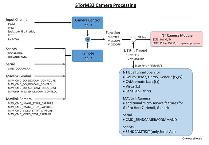
The STorM32 camera remote control is based on three elementary operations: SHUTTER, VIDEOON and VIDEOOFF. These are supported by all camera models, and can be triggered by various sources: a signal on any of the STorM32's inputs, a script, a serial command, a MAVLink message to the MAVLink Gimbal component, or a MAVLink message to the MAVLink Camera component. The NT Camera module translates these elementary operations into the corresponding output signals as required for the specified camera model. The output signals can be PWM, low-high-low pulses, UART Tx and Rx, or whatever is required.
In addition, some camera models (such as the “Runcam Split Mini2” and “GoPro Hero7”) provide a much richer set of features and functions, which the STorM32 makes accessible to the user via the MAVLink Camera Protocol microservice provided by the MAVLink Camera component. This "richer set of features and functions" is in fact most cool and not easily explained in one sentence. It for instance allows the user to access many if not all camera settings from ground control stations such as QGroundControl, like it is known for DJI drones or the 3DR Solo.
NT Camera Support by NT Imu Modules
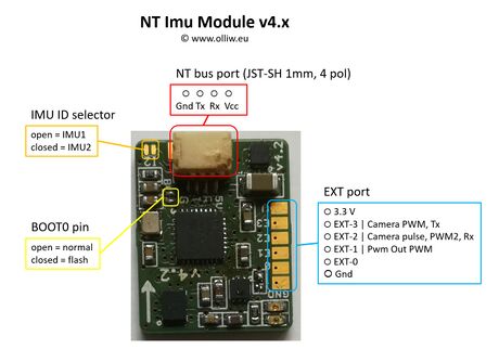
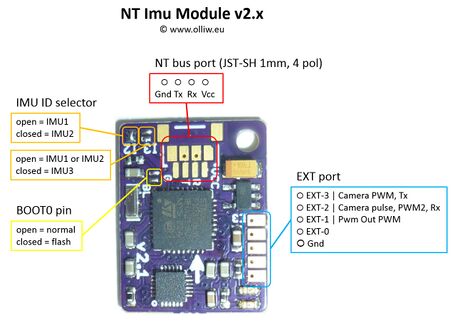
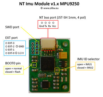
As mentioned in the introduction, the NT Camera is integrated into the NT Imu firmware. The NT Imu module provides these three signals on its EXT port pins:
- EXT-3: Camera PWM signal, or Uart Tx, or other
- EXT-2: Camera pulse signal, or Uart Rx, or other
- EXT-1: Pwm Out servo PWM signal (with ca. 60 Hz frequency)
The "Pwm Out" signal on pin EXT-1 is related to the Pwm Out Control function and is not further discussed here. See Advanced Functions: Pwm Out.
The "Camera" signals on EXT-3 and EXT-2 are related to the Camera Control and Camera Control2 functions, and depend on the Camera Model setting. For many camera models they are configured to output a PWM servo signal on EXT-3 and a pulse signal on EXT-2:
- The PWM signal can directly feed cameras which can be triggered by such signals, such as the Gitup Git2, or can be connected to common RC camera remote control modules, such as those mentioned in the introduction. The frequency of the PWM signal is ca. 60 Hz.
- The pulse signal consists of a 50 ms low/high/low pulse and can be used for all sorts of purposes. For instance, it could be connected to a semiconductor relais to drive an IR LED or shorten some pins on a USB remote.
The EXT-3 and EXT-2 pins can also assume other functions however. For instance, for GoPro cameras they are configured to operate as Tx and Rx UART signals.
The function matrix looks as this:
| camera model | EXT-3 | EXT-2 |
|---|---|---|
| Generic Rc, Git2 Rc, Mapir Survey Rc | PWM | pulse |
| CAMremote Rc | PWM | PWM2 passthrough (*) |
| Firefly Split 4K Rc | pulse | pulse |
| Pwm | PWM passthrough | PWM2 passthrough (*) |
| Runcam Generic | Tx | pulse (*) |
| CAMremote UART, Visca |
Tx | pulse (*) |
| GoPro Hero7, GoPro Hero5, GoPro Generic, Serial Api |
Tx | Rx |
Pin Assignment on the v1.x, v2.x, and v4.x NT Imu Modules
The v4.x, v2.x, and the "big" v1.x NT Imu modules expose the additional EXT port pins:
Pin Assignment for the CC3D Atom and Atom Mini
Both the CC3D Atom and Atom Mini have six servo outputs labeled PWM1 to PWM6. They are assigned as follows to the EXT port pins:
- PWM2 = EXT-1 = Pwm Out servo PWM signal
- PWM3 = EXT-3 = Camera servo PWM signal
- PWM4 = EXT-2 = Camera pulse signal
RunCam
The NT Camera can control a RunCam Split Mini2 by communicating to it via the camera's serial port. It has been confirmed to work also for a RunCam Split 2S and a RunCam Split Micro V3. It probably works for other similar cameras, but this is untested.
Set these parameters in the [GUI:Functions] tab:
- Camera Control: Set to the desired input to trigger photos or start/stop videos. Can be “off” if MAVLink is used only.
- Camera Model = “Runcam Generic”
- Camera ComPort = Set to “default” if the camera is connected to the NT Imu module, or chose the UART, UART2 or UARTX port.
If you also want the MAVLink Camera features, then in addition set these parameters in the [GUI:Interfaces] menu:
- Mavlink Camera = “Camera1” or higher
- Mavlink System ID: usually can be “0”
Comment: Some RunCam cameras such as the RunCam Split 2S provide video and photo modes. The RunCam protocol however does not allow us to reliably switch between video and photo mode, and the STorM32 therefore only supports the video mode. The implication is that the camera must be in video mode at startup.
Camera Models
The “Runcam Generic” model allows us to start and stop recording a video. The underlying UART commands should be supported by all RunCam models with UART interface, so that this model is expected to work for them all.
Wiring
The connection diagram for a NT Imu v2.x looks like this:
GoPro Hero
The NT Camera can control a GoPro camera by communicating with it via Wifi.
Here one thus requires an additional Wifi module, such as an ESP8266, Arduino MKR1000, or ESP32. The MKR1000 is quite pricey and very large, the ESP8266 works a bit dodgy, so I currently use a ESP32, which to me is the best deal. The Wifi module needs to be loaded with a particular firmware, and an Arduino sketch is available in my github repo (see link below)(currently only the ESP32 is supported, but you are of course welcome to adapt the sketch to also support e.g. the ESP8266).
If you want to know more details about the technical inside, you may read this post.
The Arduino sketches and C files (and other relevant material) are open source (GLP-v3) and available here: https://github.com/olliw42/goprohero.
WARNING: Both Wifi and most radio control systems work in the 2.4 GHz range, and interferences may thus happen and compromise your remote control signal quality. Unfortunately I could not find a single competent report or analysis of this topic on the web; all reports I found which say that it works are based on purely anecdotal evidence. So, please, be warned! In order to avoid issues as much as possible I have at least set the Wifi module's transmit power to the lowest possible level.
The Wifi module (loaded with the Arduino sketch) is connected via its serial port to the NT Camera module, i.e. the EXT-3 and EXT-2 pins on your NT Imu module (see NT Camera Support by NT Imu Modules). Alternatively, the Wifi module can be connected to the UART or UART2 port on the main STorM32 controller, which often can be the more convenient setup, as it much simplifies wiring.
Comment: Wifi modules generally need to be powered from a strong, stable power source, since current draw can be high (not on average, but in the spikes). So, do not use the NT bus 5 V power line, unless you have ensured that it is of sufficient high power or understand what you're doing.
Set these parameters in the [GUI:Functions] tab:
- Camera Control: Set to the desired input to trigger photos or start/stop videos. Can be “off” if MAVLink is used only.
- Camera Model = “GoPro Hero7”, “GoPro Hero5” or “GoPro Generic”
- Camera ComPort: Set to “default” if the Wifi module is connected to the NT Imu module, or chose the UART, UART2 or UARTX port.
If you also want the MAVLink Camera features, then in addition set these parameters in the [GUI:Interfaces] menu:
- Mavlink Camera = “Camera1” or higher
- Mavlink System ID: usually can be “0”
Camera Models
Currently three GoPro camera models are available, “GoPro Hero7”, “GoPro Hero5” and “GoPro Generic”. However, other GoPro cameras probably will work too.
The “GoPro Generic” model only provides basic support, i.e., only allows us to start and stop recording a video and taking pictures. It does so by using a Wifi command which is expected to be supported by all GoPro models with a Wifi interface. Accordingly, this model should work for all GoPro cameras.
The other camera models use Wifi settings which can be specific to the particular model, and if a model works also for other GoPro cameras thus depends on the compatibility details.
Huzzah32-ESP32 Breakout Board
The connection diagram for a NT Imu v2.x and an Adafruit HUZZAH32–ESP32 Breakout Board can look as this:
Comment: The HUZZAH32–ESP32 breakout board was the best option I found price and size wise, and that's why I use it. The connection diagram should be similar for other ESP32 boards.
CAMremote
The CAMremote from VP-Systems is a highly functional and versatile camera remote controller. The STorM32 supports it by two camera models, called “CAMremote Rc” and “CAMremote UART”.
CAMremote RC
The CAMremote provides several settings where the shutter and video on/off can be controlled via a PWM signal on the CAMremote's CH0 input. In combination with the NT Camera module, several configurations are possible, the most generic one would be to use either of these:
- CH0 = Record/AF/Shoot
- CH0 = Record/Shoot
The EXT-3 pin on the NT Imu module should then be connected to the CH0 input on the CAMremote.
The PWM2 passthrough output on the NT Imu module, or pin EXT-2, can then be connected to the CAMremote's CH1 to invoke additional features, such a manual focus, zoom in/out, and so on.
Comment: This has been tested using NT Imu firmware v0.28 and "RC receiver (CH0=Record/AF/Shoot, CH1=SmoothZoom, CH2=Alt)-mode" on CAMremote 3.0.9. In case the shutter does not trigger a photo on the camera it might be necessary to increase the focus time to give the camera time to focus.
The disadvantage of using the CAMremote with PWM input signals is that one only can toggle between VIDEOON and VIDEOOFF, and not directly set VIDEOON or VIDEOOFF, so that the actual recording state might be lost by the user.
CAMremote UART
The CAMremote also provides a serial UART interface, which provides access to a much richer set of features and functions than with the control via PWM signals.
The EXT-3 and EXT-2 pins on the NT Imu module should be connected to the Tx/Rx inputs on the CAMremote, respectively.
Currently, the STorM32 supports the 'shoot', 'recon' and 'recoff' commands.
This brings the great advantage that VIDEOON and VIDEOOFF are now set directly, and not only toggled as with the PWM input, so that the actual recording state is always known to the user.
Links
- http://vp-systems.eu/camremote.html
- http://vp-systems.eu/manual_cr.html
- https://vp-systems.eu/cr_uart.html
Visca PTZ
The NT Camera supports PTZ cameras using the VISCA protocol.
The EXT-3 pin on the NT Imu module should be connected to the Rx input on the PTZ camera (not RS232 or RS422, but UART-TTL input). The baud rate is 9600 baud. In addition, if configured in the GUI, the signal is available on a UART port on the STorM32 contoller with 115200 baud.
Set these parameters in the [GUI:Functions] tab:
- Camera Control: Set to the desired input to trigger power on/off. Can be “off” if only MAVLink is used.
- Camera Control2: Set to the desired input to zoom in or out. Can be “off” if not needed.
- Camera Model = “Visca”
- Camera ComPort = Set to “default” if the camera is connected to the NT Imu module, or chose the UART, UART2 or UARTX port.
STorM32 supports VISCA commnds to start and stop video recording, and handle zoom and focus. The VISCA commands can be issued via inputs or MAVLink commands.
The VISCA commands (supported by STorM32) have the structure
0x81 0x01 0x04 cmd-bytes 0xFF
where cmd-bytes are multiple bytes determining the task to execute. These commands are supported (only cmd-bytes are given):
0x00 0x02: video on (CAM_Power On)
0x00 0x03: video off (CAM_Power Off)
0x07 0x2p: zoom tele (CAM_Zoom Tele Variable Speed, p can be 0 ..7)
0x07 0x00: zoom stop (CAM_Zoom Stop)
0x07 0x3p: zoom wide (CAM_Zoom Wide Variable Speed, p can be 0 ..7)
0x47 0x0p 0x0q 0x0r 0x0s: zoom direct (CAM_Zoom Direct, 0xpqrs can be in range 0x0000...0x4000)
0x08 0x2p: focus far (CAM_Focus Far Variable Speed, p can be 0 ..7)
0x08 0x00: focus stop (CAM_Focus Stop)
0x08 0x3p: focus near (CAM_Focus Near Variable Speed, p can be 0 ..7)
0x48 0x0p 0x0q 0x0r 0x0s: focus direct (CAM_Focus Direct, 0xpqrs can be in range 0x0000...0xFFFF)
0x38 0x03: focus manual mode (CAM_Focus Manual Focus)
0x38 0x02: focus AF mode (CAM_Focus Auto Focus)
0x18 0x01: focus AF single (CAM_Focus One Push Trigger)
The power on/off VISCA commands are mapped to the video on/off function, available with the Camera Control input. The zoom tele/stop/wide VISCA commands are attached to the Camera Control2 input.
The full set of supported VISCA commands are available via MAVLink commands MAV_CMD_DO_DIGICAM_CONFIGURE, MAV_CMD_DO_DIGICAM_CONTROL, MAV_CMD_DO_SET_CAM_TRIGG_DIST, MAV_CMD_SET_CAMERA_MODE, MAV_CMD_SET_CAMERA_ZOOM, MAV_CMD_SET_CAMERA_FOCUS, MAV_CMD_VIDEO_START_CAPTURE, MAV_CMD_VIDEO_STOP_CAPTURE.
Comment: VISCA cameras implement the VISCA protocol in different ways and the above commands may or may not work for your camera.
Links
- https://www.epiphan.com/userguides/LUMiO12x/Content/UserGuides/PTZ/3-operation/VISCAcommands.htm
- https://www.snapav.com/wcsstore/ExtendedSitesCatalogAssetStore/attachments/documents/USBProducts/ManualsAndGuides/Visca%20Protocol2.pdf
Firefly Split 4K
The Firefly Split 4K can be controlled by two HIGH-LOW-HIGH pulses for triggering shutter and starting/stopping video recording.
The EXT-3 and EXT-2 port pins on the NT Imu module are assigned as follows:
- EXT-3: HIGH-LOW-HIGH pulse of 100 ms duration for shutter control
- EXT-2: HIGH-LOW-HIGH pulse of 100 ms duration for starting/stoping video recording
In the [GUI:Functions] tab set as follows:
- Camera Control = “Rc-0”, or whatever input port you wish to use
- Camera Model = “Firefly Split 4K Rc”
The parameters Camera Control2 and Camera ComPort are irrelevant, and the remaining parameters have their usual meaning.
The Firefly Split 4K can crash when the trigger inputs are too fast (especially when starting/stopping video, tested with firmware 20201015); the STorM32 controller thus enforces a delay of 4 seconds between the trigger pulses to prevent this.
Wiring
Connect the trigger input pins of the Firefly 4K Split camera as follows to the pins on the NT Imu module:
- green cable, rightmost pin: connect to EXT-2
- blue cable: connect to EXT-3
The PCB of the camera is conformal coated. If you want to solder directly to its connector pins, you first should remove the coating with a glass fiber pencil.
The camera board provides 3.3 V on solder pads next to the connector and 5 V on a capacitor pin (see Hawkeye's official web page linked to below). This can be used to power the NT Imu module and save one wire. Both the 3.3 V and 5 V sources work, but the 5 V is preferred.
As the NT Imu module is working with 3.3 V and thus outputs maximal 3.3 V, you can disregard the manual's warning to not connect any power to the trigger pins.
Links
- Official "How to connect Hawkeye Firefly 4K Split Cam" information: http://www.cnfpv.com/portal.php?mod=view&aid=158
Gitup Git2
The Gitup Git2 can receive a PWM signal on its Micro HDMI port to control video recording and photo triggering. The details can be found on the Gitup site. In general, a 3 position switch will be used on your transmitter: The middle position should be set to 1500 µs and will do nothing. Low position, < 1250 µs, will start recording video when switched. High position, > 1800 µs, will take a photo when switched. If your transmitter channel is setup as 0%, 50%, 100% (or -100, 0, 100) for Low, Mid, and High, then you should be fine.
Comment: To avoid misunderstanding, please note that the transmitter switch PWM values mentioned for transmitter setup are not those which are send to the camera. The STorM32 will translate the received input PWM values into those required by the camera.
Links:
- http://www.rcgroups.com/forums/showpost.php?p=34538383&postcount=3443
- https://www.gitup.com/cameras/73-gitup-git2p-standard-packing-170-degree-lens.html
Cable Information
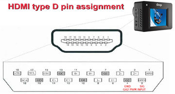
Gitup provides a Remote Shutter cable. If you choose to make your own, then please follow the pinouts for the Micro HDMI (type D) connector, not Mini or full size because they are different (see here).
- Signal In: Micro HDMI Pin 2 (usually denoted as Utility or Reserved on pinouts)
- Signal Gnd: Micro HDMI Pin 4 (TMDS Data2 Shield, or any other shield pin; even the connector's case works)
Comment: The Git2 uses its Mini USB port for both Video Out and Power In to charge or power the camera. While Gitup also provides this cable, FPV cables for the GoPro works as well. Gitup also provides a combo board/cable, which contains both the HDMI and USB connectors.
Cable and Camera Function Test
Once you have your cable and transmitter configured as above, connect your receiver or flight controller, and test it out. It should work before moving to the next step.
CC3D NT Imu, STorM32 and Git2 Camera Integration
This section is based on using the Mini CC3D Atom. Other NT Imu modules which expose the EXT pins should work equally well however. The following is only one of the several possible configuration options available with the STorM32.
Comment: Your STorM32 and NT Imu module need to communicate correctly, it is however not mandatory that the gimbal has been configured or tuned.
Wire up as follows:
- Connect your receiver, or flight controller, to one of the seven STorM32 RC ports (RC-0 through RC2-3), or use any other input channel (see Inputs and Functions).
- Connect the Git2 Remote Shutter cable to the EXT-3 and GND pins on the NT Imu module (see NT Camera Support by NT Imu Modules).
In the [GUI:Functions] tab use the column for Camera Control and set as follows:
- Camera Control = “Rc-0”, or whatever input port you wish to use
- Camera Model = “Git2 Rc”
The parameters Camera Control2 and Camera ComPort are irrelevant, and the remaining parameters have their usual meaning.
Foxeer Legend 1
This should work as for the Gitup Git2, with identical settings. This has not yet been tested though.
Mapir Survey
The Mapir Survey is in many regards similar to the Gitup Git2. For instance, it also can receive a PWM signal on its Micro HDMI port for control. However, the PWM signal required by the Mapir is quite different to that for the Git2. Furthermore, only photos can be triggered, but video recording cannot be started/stopped. Thus, the Git2 camera model cannot be used for the Mapir.
The electrical connections and setup are largely identical to the Git2, so please look up there. These differences might be noteworthy:
In general, a 2 position switch will be used on your transmitter: The middle position should be set to 1500 µs and will do nothing. High position, > 1800 µs, will take a photo when switched.
In the [GUI:Functions] tab use the column for Camera Control and set as follows:
- Camera Control = “Rc-0”, or whatever input port you desire
- Camera Model = “Mapir Survey Rc”
The parameters Camera Control2 and Camera ComPort are irrelevant, and the remaining parameters have their usual meaning.
Comment: To avoid misunderstanding, please note that the transmitter switch PWM values mentioned for transmitter setup are not those which are send to the camera. The STorM32 will translate the received input PWM values into those required by the camera.
Links
- https://www.rcgroups.com/forums/showthread.php?2055844-STorM32-BGC-32-bit-3-axis-brushless-gimbal-controller/page232&perpage=50#post42713367
- https://www.mapir.camera/pages/survey3-cameras
- https://cdn.shopify.com/s/files/1/0878/4732/files/MAPIR_Survey3_Manual_v1.pdf
Serial API
The “Serial Api” is a special camera model, designed to inter-operate with an external computing device, such as a Raspberry Pi, Arduino, and alike, via a serial data line (in the following the example of a Raspberry Pi, denoted as RPi, is chosen). The prototypical application example would be to integrate gphoto-controlled cameras into the STorM32 system.
The RPi is connected to the UART on the STorM32 controller which is selected in the parameter Camera ComPort. The serial API camera model then provides a set of commands to exchange information between the STorM32's NT Camera functionality and the RPi. On the RPi a script is running which handles the communication, i.e., translates the commands of the serial API into the corresponding actions needed for the specific camera which shall be operated, and vice versa.
In the [GUI:Functions] tab set as follows:
- Camera Model = “Serial Api”
- Camera ComPort: Select the UART (“default” is currently not supported)
The serial API currently consists of the following:
- "shutter\n", "videoon\n", "videooff\n": These commands correspond to the STorM32's internal SHUTTER, VIDEOON and VIDEOOFF states, and are send whenever the respective state is assumed. This can be via an input as selected in the parameter Camera Control, a serial command, a MAVLink command, or via the MAVLink Camera microservice.
- "cntrl2high\n", "cntrl2low\n", "cntrl2stop\n": These commands are send according to the state of the input selected in the parameter Camera Control2.
- SENDCAMTEXT: This script command sends a user-defined string to the RPi (the string is appended by a '\n' character). This allows us to use the potential of scripts for controlling the camera handled by the RPi.
An example Python script which can be run on a RPi is available in the firmware .zip file.
UartX Configuration
The number of available UART ports on STorM32 boards is limited, especially on v1.3 boards, and it can thus happen that one is running out of them.
In such cases, the RC-0 and RC-1 input pins can be reconfigured to work as a further UART port, then named UARTX. This comes at the obvious cost that these inputs cannot be used anymore as PWM, Spektrum, SBus, and alike inputs.
For this, set:
- UartX Configuration = “uartX @ 115200” (the parameter is located in the [GUI:Setup] tab)
- Camera ComPort = “uartX”
The physical assignment is
- RC-0 = UARTX Rx
- RC-1 = UARTX Tx
For the location of the RC-0, RC-1 pins on your board please refer to Pins and Connectors.
Stand-alone Use
The NT Camera can also be used stand-alone, without a gimbal. This effectively allows us to convert any of the supported cameras into a MAVLink camera.
This mode of operation can be especially useful for those camera models which provide features beyond the basic SHUTTER, VIDEOON, and VIDEOFF operations, such as the Runcam Split Mini2 or the GoPro Hero models.
The camera and MAVLink settings are as described in the above for the respective camera model. Typically, the UART port would be used for the MAVLink connection to a flight controller, and the UART2 port for connecting to the camera.
The main difference in setup would be to also disable the motors, by setting in the [GUI:Setup] tab:
- Pitch Motor Usage = “disabled”
- Roll Motor Usage = “disabled”
- Yaw Motor Usage = “disabled”
Wiring
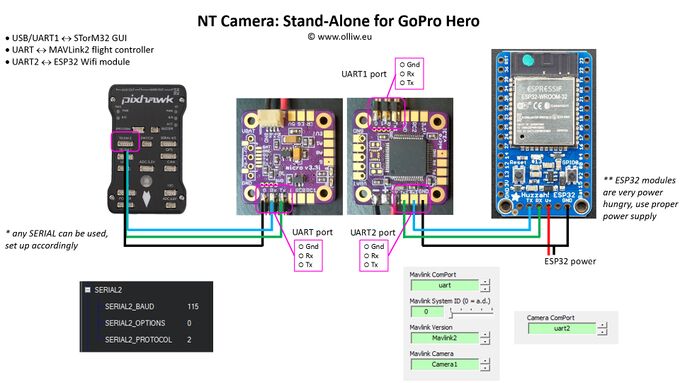
For a v3.x STorM32 board the connection scheme could be as this, here shown for the example of the GoPro Hero model:
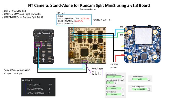
For a v1.x STorM32 board the UARTX configuration capability can come in handy. The setup for a Runcam Split Mini2could look like this:
Links
IR Led Support
IR Leds are not natively supported. It is possible though to use any of the RC camera remote controller (some were listed on the top of the page). You also can make use of the pulse signal on (some of) the NT Imu modules or STorM32 boards and connect it to a semiconductor relais to drive a IR Led. It is also easy to build your own IR controller e.g. using an Arduino, which then even can be made easily to use a serial camera model.
Comment: STorM32 v1.x boards have a dedicated IR Led driver on board, which in earlier firmware versions could be used to control cameras like the Sony Nex by IR remote. With version v2.61h IR Led support has been removed.
Code Examples
Please see Code Examples: NT Camera.
