Pins and Connectors of NT Modules
A potentially confusing variety of NT modules are around. Generally they can be distinguished into what could be called "generic" modules (i.e. modules designed by the firmware author himself), modules by third parties which either are derived from the "generic" modules or are independent designs, and lastly modules which are build by using hardware from other projects.
For the "generic" modules the version number serves two purposes:
- It distinguishes the version of the particular design. For instance, a v2.5 motor module is a later design than a v2.4 motor module. It either may have just minor corrections and improvements as compared to the v2.4 module, but also might be a totally different design.
- The major version number distinguishes the electric scheme and therefore which firmware has to be run on them. For instance, a v2.4 and v2.5 motor modules are different designs but are based on the same electric scheme and thus need to be loaded with the same firmware. In contrast, the v1.x and v2.x IMU modules are different in design and also have different electric schemes, and hence need to be flashed with different firmwares.
A "x" in a version number is generally used as a placeholder for any subversion number.
NT v4.x Modules
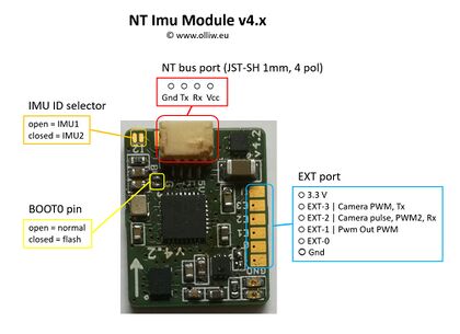
The NT v4.x modules are similar to the v2.x and v1.x modules, but are based on STM32G4xx chips instead of the STM32F103 used before. They generally use more modern hardware.
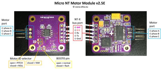
Micro NT v2.x Modules
NT v2.x Modules
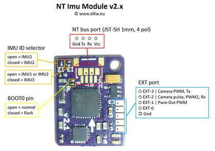
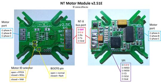
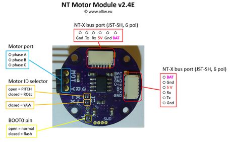
The NT v2.x modules can have a 4 pin JST-SH plug for the NT bus connector, and a 6-pin JST-SH header for the NT-X bus, with the pin assignments as shown below. The connections might also be exposed as solder pads. The modules in addition usually offer a BOOT0 solder jumper (the bootloader listens on the NT bus (UART1) pins), and some expose the SWD pins, to allow for a first-time flashing. Some modules offer some further solder jumper for configuring them, and some may provide access to additional extension pins.
NT v1.x Modules
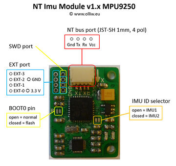
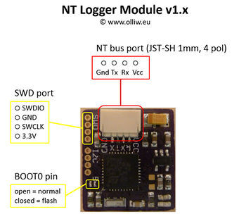
The NT v1.x modules have a 4 pin JST-SH plug for the NT bus connector, with the pin assignments as shown below. They in addition offer a BOOT0 solder jumper (the bootloader listens on the NT bus (UART1) pins), to allow for a first-time flashing. Some modules offer some further solder jumper for configuring them, some others expose also the SWD pins, and yet some others may provide access to additional extension pins.
CC3D Atom NT Imu Module
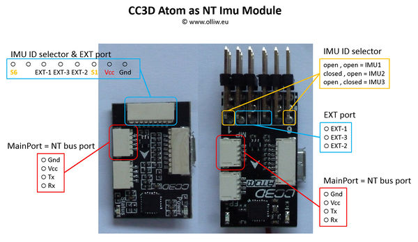
On the CC3D Atom boards the Main Port plug is used as NT bus connector, with the pin assignments as shown below. Further information on the CC3D Atom can be found here.
Comment: To close the IMU ID selector, connect the indicated pin to GND.
