Talk:Getting Started
In my opinion the original text for the IMU orientation was correct, the example image was not. Take the first example, the dot is at the left bottom, hence the y-axis points to the left. Correct. But the x-axis is drawn to point upwards, originating in the white dot instead of ending there.
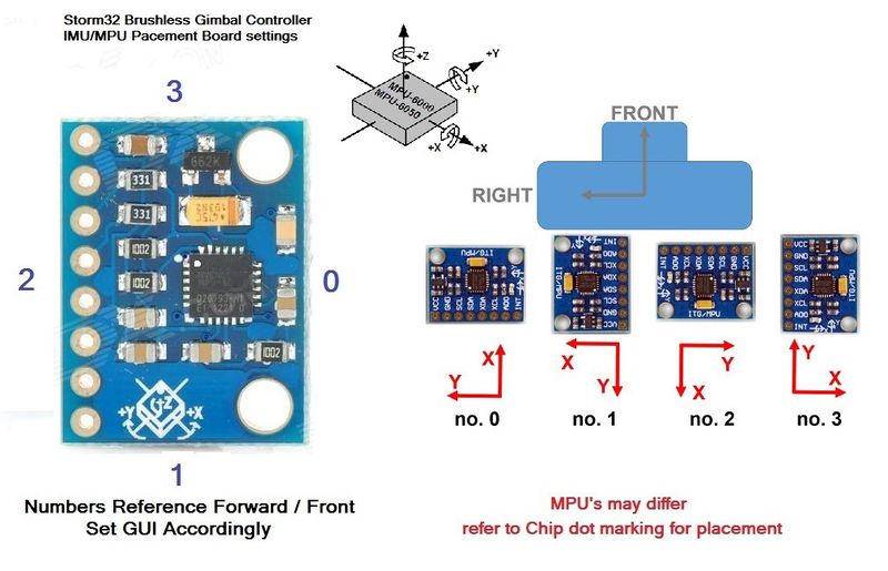
On every MPU6050 chip (STorm32BGC or breakout module) you can find a little dot (white point) in one corner. This dot shows the direction of the y axis (the corner shows to the end of the y line, its not the origin). The x axis is always face to face to the y axis, diagonal (the corner shows to the end of the x line, its not the origin). To better understand this inspect the schematics in the middle of the picture below, where the y axis (white dot) points to the up-right, and the x axis to the down-right. The z axis is always points away from the face of the chip. Now it is easy to get the right GUI settings.
Example: The IMU is on top of the camera and the white dot on the chip is, when looked at the camera from the font, showing to the left and to the roll axis. Then the IMU gui setting is no.1 (z axis points up / x axis points right).
Further examples are treated in this picture:
