Manually Setting the IMU Orientation
Since v0.56 the GUI offers the [Configure Gimbal Tool], which allows you to set the IMU oriantation of both the camera and 2nd IMU very easily. On this page the method is described to set, and check, the correct IMU oriantation(s) manually.
It is of outmost importance to set the IMU orientation(s) correctly, else the controller has no chance to work correctly. So, please double and triple check that you got the IMU setting right!
The procedure is identical for the camera and 2nd IMU. The description is for the camera IMU; it is straight-forwardly carried over to the 2nd IMU.
Determining the IMU Orientation
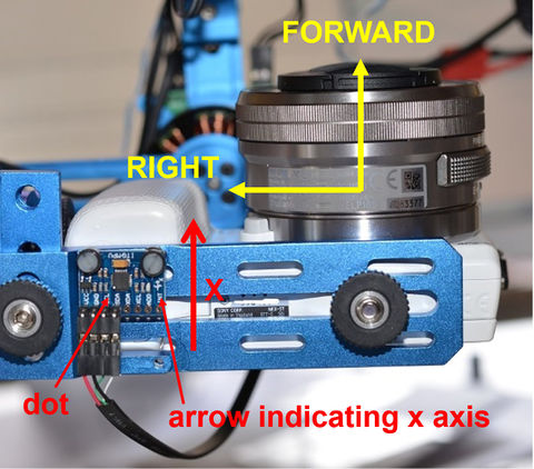
First ensure that all motors are disabled or disconnected to avoid any motor movements. Then investigate your IMU board/module. There is usually an arrow printed on it for the x axis. If not, you may use the little dot marker on the IMU chip as reference (see the Appendix below). Next, hold the gimbal and camera in front of you, as if you would be taking a picture. "Up" refers to the top of the camera, "forward" to its front with the lens, and "right" to the right-hand side of the camera. Finally, go to the [Gimbal Configuration] tab. In the bottom you find the fields [z axis points] and [x axis points]. The questions to answer now for setting the IMU orientation are where its z axis and x arrow point to.
The IMU's z axis points outwards of the surface of the IMU chip, i.e., comes straight out of the IMU board. In the example below, as the IMU board is mounted upside down, it points downwards the camera, so in the GUI you specify that the [z axis points] "down". For the x axis we use the printed arrow on the IMU board. In the example below it is pointing in the camera's forward (shooting) direction, hence in the GUI you set that the [x axis points] "forward". The little graphic on the right displays your setting, i.e., the IMU's x-y-z axes with respect to the camera's up-right-forward orientations.
Selecting the fields [z axis points] and [x axis points] determines the IMU orientation index, here no. 15, and writes it into the Imu Orientation parameter field located in the left top corner in the [Gimbal Configuration] tab.
To send the setting to the board click on the [Write] button. In order to make the changes permanent, the menu option [Store to EEPROM] can be used. Alternatively, click on the check box next to the [Write] button, which causes the button label to change to [Write+Store], and hit the button. Both methods are fine.
Checking the IMU Orientation
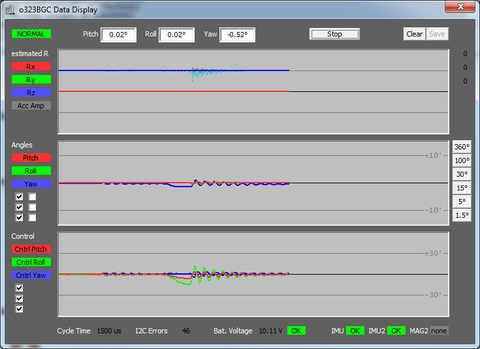
In order to ensure a correct IMU orientation you should test it. Write the setting to the controller (temporarily or into the EEPROM) and then click on the [Data Display] button. This opens a realtime monitor window. In the top you can see the current Pitch, Roll, and Yaw angles once you did click on [Start] in the window.
As the motors are (hopefully) disabled still, you can move the camera by hand. The following behavior must be observed:
- When you tilt the camera downwards (lense points to the ground), the Pitch value has to get more positive (the red line in the middle panel of the Data Display has to move upwards).
- When you roll the camera like in flying a right turn (clockwise when standing behind the camera), the Roll value has to get more positive (the green line in the middle panel of the Data Display has to move upwards).
- When you rotate the camera around the yaw axis anti-clock wise, the Yaw value hast to get more positive (the blue line in the middle panel of the Data Display has to move upwards).
If you do not observe that, then go back and repeat the IMU orientation setting.
Comment: When checking the setting for the 2nd IMU don't forget to click the respective checkbox in the Data Display.
Appendix
In case your IMU board has no arrow printed on it or you are uncertain, when you can also use the white dot in one of the corners on the IMU chip (MPU6050) to determine the orientation. In the diagram below the axes and their orientation in relationship to the dot are shown as sketch and for some examples.
As said before, the z axis comes out of the top surface of the chip and the x axis points away from the dot. Check the chip labels, the x axis runs in the reading direction of the labeling.


