Pins and Connectors
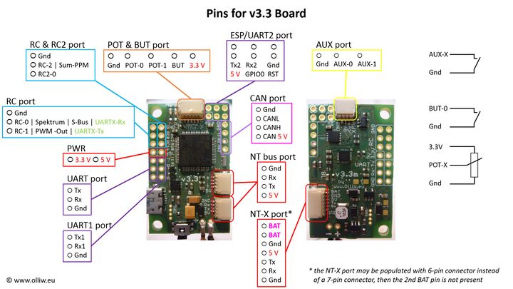
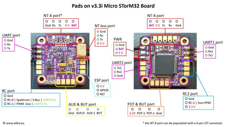
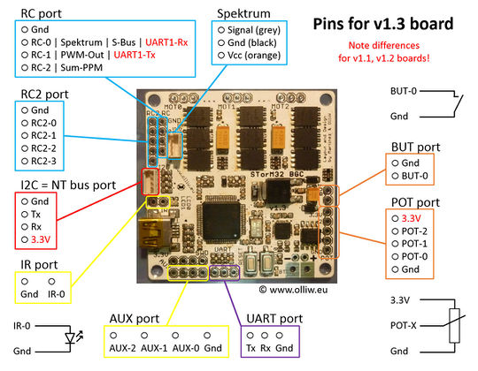
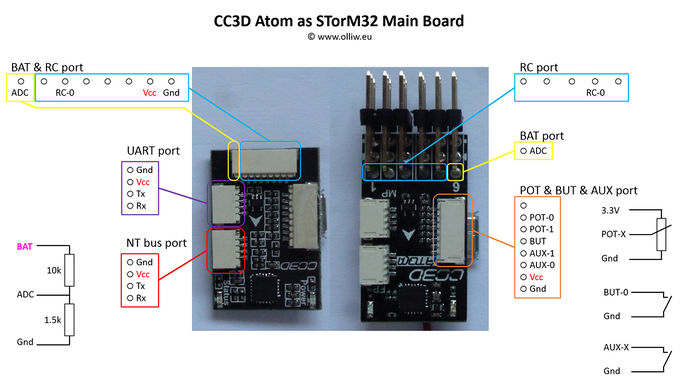
This page provides diagrams of the many connections on the STorM32 boards.
The STorM32 connections are grouped into ports. A port consists typically of one or more pins, a Gnd pin and possibly a 3.3 V or 5 V pin. The pins of a port are labeled by the port name plus a number (e.g. AUX-0 refers to the pin 0 on the AUX port) or by its commonly known function (such as Gnd, 3.3 V, Tx, Rx, SCL, SDA etc.). Some pins can serve multiple purposes, e.g., pin RC-0 serves also as Futaba S-BUS input or as UARTX-Rx.
For a general description of the ports and pins see Ports and Pins by Function. For the details of their function and usage please consult the other wiki pages.
Except of the ports POT, BUT and ESP/UART2 all ports are 5 V tolerant, which means that you can apply signals with voltages of up to 5 V to their pins without damaging the board. The ports POT, BUT and ESP/UART2 are however not 5 V tolerant. The voltage on the POT, BUT and ESP/UART2 pins must not exceed 3.3 V.
The 3.3 V and 5 V pins must only be used as supply. Never apply any voltage to a 3.3 V or 5 V pin (unless you're an expert and know what you do).
STorM32 v3.x Boards
The STorM32 v3.3 main board provides two types of NT bus ports, the NT and NT-X ports. They both are different from the NT bus connectors found on the NT modules in as much as they have swapped Rx, Tx pins.
Comment: The Rx, Tx pins of the NT/NT-X port on the STorM32 board must be connected to the Tx, Rx pins on the NT modules.
Comment: The v3.x STorM32 board has no motor drivers on-board, i.e., NT motor modules are needed in addition.
Micro STorM32 v3.x Boards
The v3.3i Micro STorM32 board provides the same connections as the v3.3 Board (with the exception of the USB and CAN ports), but exposes them as solder pads.
The Micro STorM32 board is desoigned to be stackable with other extension boards, such as USB, power, motor, logger boards, see e.g. this rcgroups post here.
Comment: The v3.x Micro STorM32 board has no motor drivers on-board, i.e., NT motor modules are needed in addition.
STorM32 v1.x Boards
On STorM32 v1.3x main boards, the I2C plug is used as NT bus connector, with the pin assignment as shown below.
The scheme below refers to a v1.3 board. The pins of the v1.31 board are identical to that of the v1.3 board.
Comment: The Rx and Tx pins on the STorM32 board must be connected to the Tx and Rx pins on the NT modules. This needs a "crossing" of the Rx, Tx lines for the v1.x boards, see also the diagram in What is STorM32 NT about?
Comment: If starting from a "classic" (non-NT) STorM32 gimbal kit with an I2C IMU module, it is usually necessary to rewire existing cables to match the pinout of the NT bus.
Comment: v1.1 and v1.2 boards are deprecated and not supported anymore.
CC3D Atom STorM32 Board
Since firmware version v2.27 it is possible to use a Atom CC3D as STorM32 main board. The Flexi Port plug is used as NT bus connector, with the pin assignments as shown below. Further information on the CC3D Atom can be found here.
Comment: The CC3D cannot be used anymore with the latest firmwares. This is obviously so because the feature set has grown enormously taking up too much flash space. The v3.3 board should be an excellent alternative.


