Configure the RC Input
The orientation of the camera can be controlled by a variety of external input signals such as from a receiver, a joystick, or keys. The source of the input signal and the exact behavior of the camera in relation to the input is configured in the [Rc Inputs] tab, which is described in the next chapter. Physically the signal sources need to be connected to certain pins on the controller. The various possibilities are described in the subsequent chapters. For a general overview of the available pins on the controller consult Pins and Connectors.
GUI Settings
- [Rc Mid Mode]: Controls how the board figures out the neutral or center position of the input signal. Currently this setting doesn't have any effect and is to be ignored.
- [Rc Dead Band]: Defines how wide the neutral range of the input signal is. It becomes relevant e.g. then transmitter/receivers are used to control the relative movements, the Yaw axis usually. If you find a slow but constant movement on the Yaw axis because the transmitter stick does not re-position itself perfectly to center, then increase the deadband range a bit. 10us requires a very precise setting, double it or more. Applies to all input channels, also a joystick.
- [Rc Pitch Trim], [Rc Roll Trim], [Rc Yaw Trim]: These values allow for a fine adjustment of the neutral camera orientation for each axis.
There are further fields for precisely configuring the camera movements. They are identical for each axis, Pitch, Roll and Yaw (with one exception). Let's use Yaw as example:
- [Rc Yaw]: This defines what pin this signal is taken from, and wherewith implicitly of what type it is (PWM, Sum-PPM, analog, digital).
- [Rc Yaw Mode]: In "relative" mode the stick in neutral position means no movement, and the stick fully to one side to move at the highest possible speed. So this is the proper mode for a stick that positions itself back to center automatically. In "absolute" mode the stick in neutral means to position the camera exactly in forward orientation, and the stick held completely to one side has the meaning of looking at the min (or max) degrees as set by the [Rc Yaw Min] and [Rc Yam Max] values. For the Yaw axis also the setting "relative turn around" is available, which effectively switches off the Min/Max limits. In this mode the camera can be turned around indefinitely.
- [Rc Yaw Min], [Rc Yaw Max]: The minimum and maximum value in degrees allowed for yaw movements. You can move the camera between these two extremes only. If the minimum value is greater than the maximum value, then the direction is reversed.
- [Rc Yaw Speed Limit]: The maximal speed with which the camera is turned in degrees per second. When panning the camera you do not want an extremely fast turn rate, a swish pan almost. Neither would that be controllable via a stick nor would the gimbal be able to cope with the forces. Hence you have the option to limit the turn rate to an upper speed limit.
- [Rc Yaw Accel Limit]: The maximal acceleration with which the camera can be moved. The larger the value the more the the acceleration is reduced. Just because the stick was moved from full left to full right, the camera should not make the same abrupt movements. It should slowly turn faster and faster according to the given acceleration limit, as well as should slowly get slower and slower.
As an example the pitch and yaw axis shall be controlled by a transmitter. The receiver outputs shall be connected to the controller board at the Rc2-0 and Rc2-1 pins for pitch and yaw control, respectively.
Wiring for RC PWM Signals
A RC receiver has multiple three pin headers, each single one providing GND (black wire), +5V (red wire) and the RC signal (white wire). Internally all GND pins are connected. To save space and reduce the number of cables required, the STorM32-BGC board has one pin for GND only plus the various signal pins.
Therefore a typical connection will look like
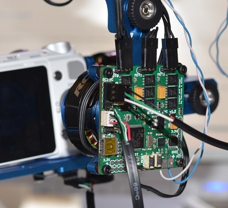
- Any receiver's GND pin connected to RC2-GND, that is the pin next to the label (see image below, the black GND cable is the top most)
- The receiver's channel 3 signal pin connected to RC2-0 (green cable below) used for pitch
- The receiver's channel 4 signal pin connected to RC2-1 (white cable below) used for yaw
- Roll is usually not controlled by the RC and hence not connected. Or do you see a reason why the camera horizon should not be level?
Note: The +5V line between receiver and STorM32-BGC board is *NOT* connected. The BGC board is powered by the battery directly, the receiver by a BEC module, usually part of the ESC.
