Using STorM32 with BetaPilot
The information on this page refers to firmware v2.59e and BetaPilot (BetaCopter/BetaPlane) 4.0 v0.50, and higher.
The STorM32 gimbal controller can communicate with ArduPilot flight controllers via a serial UART data link using the MAVLink protocol. The serial communication allows for a much richer data transmission and accordingly richer set of features than possible with the traditional connections such as PWM, PPM, SBUS, and alike. Examples are advanced control functions, the STorM32-Link or the NT Camera features. It also can lead to a much cleaner wiring and a more robust and reliable system.
The ArduPilot firmware is however quite limited as regards its gimbal and camera support (and also flawed), and thus BetaPilot was started many years ago.
BetaPilot, which includes BetaCopter and BetaPlane, is a fork of ArduPilot, with modifications which are specifically directed at the STorM32 gimbal controller. If you want to make best use of your STorM32 gimbal and want 2020-ish capabilities, then you definitely want to chose BetaPilot (BetaCopter/BetaPlane). :)
This article is about BetaPilot. For info on using the original ArduPilot firmware with STorM32, please visit the article Using STorM32 with ArduPilot. A feature matrix comparing the two is found here: Feature Matrix.
BetaPilot
BetaPilot implements the latest MAVLink standard as well as the STorM32 MAVLink2 mount type (MNT_TYPE = 83), which make the features below possible.
In order to establish a working communication between the STorM32 controller and the flight controller, a serial connection needs to be established, and parameters in both the flight controller and the STorM32 controller need to be adjusted, as described in the subsequent chapters.
BetaPilot is currently available for copters and planes. The code additions are however such that it should be trivial to extend to other vehicles supported by ArduPilot. BetaPilot currently comes in these branches:
- BetaCopter4.0: This is based on ArduCopter 4.0.7 stable, and is hence the go-to version for copter users.
- BetaPlane4.0: This is based on ArduPlane 4.0.9 stable, and is hence the go-to version for plane users.
- BetaCopter4.1: This is based on ArduCopter 4.1.0 beta (= not stable).
- BetaPilot: This is based on ArduPilot master, which is ArduPilot's development branch (= not stable). The support of BetaPilot is not steady but more like on and off. Typically, BetaPilot is progressing when required features are in master but not yet in the stable branches, but otherwise it tends to lack behind.
Firmware Binaries
For BetaCopter and BetaPlane, ready-to-use firmware binaries are provided for some few boards in the 'compiled_binaries' folders:
For other boards, the respective source code needs to be compiled by the user. For instructions on how to compile BetaCopter or BetaPlane, please consult the github repository, https://github.com/olliw42/BetaPilot/wiki.
For installing/flashing the binary follow the common instructions for installing custom firmware. In MissionPlanner, e.g., go to 'Setup -> Install Firmware -> Load custom firmware'.
COMMENT
Before using BetaCopter/BetaPlane, it is strongly recommended to first install the original ArduPilot firmware and get the vehicle operating flawlessly with it. Only then install BetaCopter/BetaPlane.
The additions by BetaPilot (BetaCopter/BetaPlane) to the main code are minimally infectious, meaning that they do not have impact on normal behavior. It is usually no problem at all to swap the firmware between ArduCopter/ArduPlane and BetaCopter/BetaPlane, which can help sort out issues in case of doubt of the origin of an issue. The main impact of BetaCopter/BetaPlane is a slightly increased flash and RAM footprint, which can have effects on boards which are short of flash and/or RAM. That's a general problem with this kind of boards.
STorM32 MAVLink2 Mount Type
The STorM32 controller needs to be connected via one of its serial ports to one of the serial ports on the flight controller, and these settings be made:
Settings in STorM32:
- Mavlink Gimbal = “Gimbal1” or higher
- Mavlink Gimbal Stream = “attitude” or higher (“mountstatus” or higher is recommended)
- Mavlink Uart Port = “uart” if the serial port UART is used (this is the default)
- Mavlink System ID = “0” for auto-detection or system ID of autopilot
Other MAVLink-related settings can normally be left at their default. A complete description of the parameters is provided in MAVLink Communication: Parameters (please read it, just in case).
The STorM32 controller needs to be rebooted when you change Mavlink Uart Port. Changes to the other settings become effective immediately. However, depending on the situation, you may have to reboot the complete system (gimbal and flight controller and GCS) to also reset internal states and auto-detection mechanisms in these components in order for all to work properly.
Comment: Selecting “attitude” in Mavlink Gimbal Stream can confuse some ground control stations, e.g. QGC, since they fail to distinguish between the flight controller's and the STorM32's attitude message. In this case choose “mountstatus” or higher.
Settings in BetaPilot:
- MNT_TYPE = 83
- MNT_ZFLAGS = 0
- SERIALx_PROTOCOL = 2
- SERIALx_BAUD = 115
SERIALx can be any of the available serial ports SERIAL1, SERIAL2, and so on ('x' stands for 1, 2, ...). This enables the STorM32 MAVLink2 mount. The flight controller must be rebooted for the changes to become effective.
The default baudrate of the STorM32 serial ports is 115200 bps, hence in ArduPilot SERIALx_BAUD has to be set to 115. However, other baudrates can be configured. For instance, for 230400 bps one sets the STorM32 parameter Uart Baudrate to “230400” and the ArduPilot parameter SERIALx_BAUD to 230.
With these settings you should notice this:
- In MissonPlanner or any other GCS, a additional MAVLink component named GIMBAL will be present.
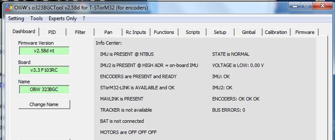
- In the STorM32 [GUI:Dashboard], the MAVLINK field will show PRESENT.
- In the STorM32[GUI:Dashboard], the STorM32-Link field will show PRESENT or a similar positive message.
This provides quick indicators for whether things are working or not. For further testing options, please see Testing the Connection.
The above settings establish the basic configuration. Some features need additional parameters to be adjusted, which will be described in the following chapters.
Further Settings in BetaPilot to Consider:
Please disable (set to 0) the SRx streaming parameters for the serial port you are using for STorM32. This avoids that the STorM32 controller is bombarded with superfluous messages and helps it to achieve consistent behavior. Depending on the vehicle type and ArduPilot firmware version you may find that the streaming parameters are enabled or disabled by default. So, please check.
Depending on the details of the ArduPilot setup it occasionally can come to DMA contention issues (has nothing to do with BetaPilot, is low-level ArduPilot behavior), which especially can make STorM32-Link to not work properly. If you have hints that such an issue exists in your case, you can try this: Disable all unused serial ports (SERIALx_PROTOCOL = -1)(this is generally a good advice to do). You also may try enabling the TX_NoDMA flag in the SERIALx_OPTIONS parameter (and maybe also the RX_NoDMA flag). It also can help to simply use a different serial port on the flight controller (different SERIALx). Please do not hesitate to join a STorM32 discussion thread at rcgroups for further discussion.
STorM32-Link
Requires this additional setting:
Settings in STorM32:
- STorM32Link Configuration = “v1”
With MNT_TYPE = 83, the flight controller also sends out the STorM32-Link data to the STorM32 gimbal, but these data are used by the STorM32 controller only when STorM32Link Configuration = “v1” is also set.
Comment: This setting does not affect the message shown in the [GUI:Dashboard] STorM32-Link field! The message shown there, such as 'not available', PRESENT, INUSE, OK, reflects the incoming data stream, not its usage.
For more details on the STorM32-Link, please read the article STorM32-Link.
Virtual Channel Configuration
Requires this additional setting:
Settings in STorM32:
- Virtual Channel Configuration = “serial”
With this setting, all STorM32 functions can be invoked by selecting any of the “Virtual-1” - “Virtual-16” input channels, exactly as one would do it if the STorM32 controller would be directly connected to a receiver by traditional means (PWM, PPM, sbus, and so on).
This allows us to do many useful things, such as activating a script or triggering video on/off from the transmitter. It however also allows us to do nonsense, and it is in the user's responsibility to avoid that.
For instance, if ArduPilot is in Rc Targeting mode, and e.g. Rc Pitch Control is set to a virtual input channel, then the gimbal may move in funny ways since it may receive the transmitter stick information from both ArduPilot and the receiver. On the other hand, if ArduPilot is in GPS or ROI Targeting mode, then one gets "free look", which is useful and quite cool actually. As said, all this is exactly as if the receiver would be directly connected to the STorM32 controller on its RC ports.
Passthrough Configuration
This feature allows you to connect the STorM32 GUI to the USB or any (MAVLink enabled) serial port of the flight controller, and to directly communicate with the STorM32 gimbal.
This is extremely convenient for configuring STorM32 gimbals when they are e.g. installed permanently in the vehicle. This also works via a wireless telemetry link, and thus opens the option of e.g. tuning the gimbal during flight, and further unheard of possibilities for controlling the gimbal during flight.
This preliminary demo video demonstrates the pass-through feature:
Prearm Checks
Requires this additional setting:
Settings in STorM32:
- Prearm Check != “off”
Settings in BetaPilot:
- MNT_ZFLAGS = 128 (this is a bitmask, so 128 means that the 8-th bit should be set by adding 128 to the value)
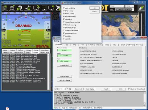
The STorM32 controller supports a rich set of prearm checks. The status of the prearm checks is passed on to the flight controller, and lets it handle them exactly like it handles any of its other prearm checks. For instance, in a GCS it will display a message "PreArm: Mount prearm checks failed" in intervals of 30 seconds.
This provides a simple and quick check that the STorM32 gimbal is working as intended.
For more details on the prearm checks, please read the article Prearm Checks.
Statustext Messages
With MNT_TYPE = 83, the flight controller sends various MAVLink STATUSTEXT messages to a ground control station, providing additional information.
In addition, MAVLink STATUSTEXT messages can also be send via STorM32 scripts, the SENDMAVTEXT command specifically. This provides a very versatile mechanism to communicate to the user.
STorM32 MAVLink Gimbal Protocol
With BetaPilot installed, the flight controller supports the STorM32 MAVLink Gimbal Protocol. It can be enabled and configured via the MNT_ZFLAGS bitmask parameter.
For more info see MAVLink Communication: Gimbal Protocol V2.
MAVLink Camera Microservice
BetaPilot implements the MAVLink protocol as specified in the original MAVLink standard. Therefore, with BetaPilot installed, also the MAVLink Camera Microservice can be fully used.
The STorM32 gimbal controller also implements a MAVLink Camera controller, which is described in much detail in the articles MAVLink Camera and NT Camera.
Testing the Connection
The serial MAVLink connection can be tested in several ways. The following tests do not require that the vehicle is completely built and/or set up, and do not require that the vehicle is armed.
MAVLINK field in STorM32 GUI
The [GUI:Dashboard] has a field named MAVLINK. It should display PRESENT.
Comment: MAVLINK is PRESENT (only) means that the STorM32 controller has a system ID and is receiving some MAVLink messages. It does not mean that the STorM32 controller makes any use of the received messages. The gimbal or camera component must be enabled for that.
STorM32-LINK field in STorM32 GUI
The [GUI:Dashboard] and [GUI:Data Display] each have a field which is related to the STorM32-Link. They should display PRESENT, AVAILABLE or OK.
Comment: STorM32-Link is PRESENT, AVAILABLE, OK (only) means that the STorM32 controller is receiving the STorM32-Link data and what their quality is. It does not mean that the STorM32-Link data are used. If it is used or not is determined by the setting in STorM32Link Configuration.
Mavlink Inspector in STorM32 GUI
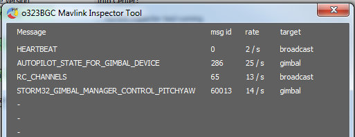
The [GUI:Mavlink Inspector Tool] displays the MAVLink messages which the STorM32 controller receives and can handle.
Comment: Only MAVLink messages are displayed which the STorM32 controller can handle. The fact that messages are displayed does not mean that the STorM32 controller does handle these messages. This depends on the settings.
MissonPlanner or QGroundControl
With the Gimbal component enabled, a MAVLink component named GIMBAL or GIMBALx (x = 2...6) should be present. If the Camera component is enabled, a component named CAMERAx (x = 1...6) should be present.
In MissionPlanner for instance:
MissonPlanner Messages Box
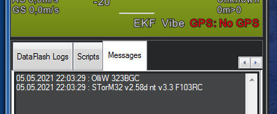
With the GIMBAL (or CAMERA) component selected in MissionPlanner, the Messages box should show several text messages related to the STorM32 gimbal. In particular, a message like "STorM32 v2.40 nt v1.30 F103RC" informing about the STorM32 firmware version should be visible.
Comment: You need to select the gimbal or camera component in MissionPlanner. If you select the autopilot component, you will also see messages which are related to the mount, i.e., which are of more generic nature and not STorM32 specific.
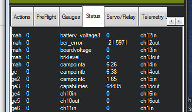
Campoint in MissonPlanner Status Box
With the autopilot component selected in MissionPlanner, the campointa/b/c values in the Status box should show non-zero values and should move according to the movement of the gimbal.
Comment: If you select the gimbal component in MissionPlanner, then it will depend on your configuaration what you will see happening in MissionPlanner when the gimbal moves.
Gimbal RC Targeting
With the autopilot in RC Targeting mode (which should be the default mode), the gimbal can be moved with the transmitter sticks.
Gimbal Point
MissionPlanner supports what it calls a 'gimbal point'. It is a blue point icon on the map, which indicates the estimated position at which the gimbal is looking at (see also e.g. https://github.com/ArduPilot/MissionPlanner/issues/1323). In order to activate it, the following ArduPilot parameters must be set:
Settings in ArduPilot:
- MNT_STAB_ROLL = 0
- MNT_STAB_TILT = 1
