NT Data Logging: Difference between revisions
| Line 77: | Line 77: | ||
|{{PARAMVALUE|basic}} || SetLogger, CmdAhrs, SetMotorAll | |{{PARAMVALUE|basic}} || SetLogger, CmdAhrs, SetMotorAll | ||
|- | |- | ||
|{{PARAMVALUE|acc & gyro raw}} || CmdAccGyroRaw | |{{PARAMVALUE|acc & gyro raw}} || CmdAccGyroRaw for Imu1 & Imu2 | ||
|- | |- | ||
|{{PARAMVALUE|pid}} || CmdPid | |{{PARAMVALUE|pid}} || CmdPid | ||
|- | |- | ||
|{{PARAMVALUE|acc & gyro}} || CmdAccGyro | |{{PARAMVALUE|acc & gyro}} || CmdAccGyro for Imu1 & Imu2 | ||
|} | |} | ||
Revision as of 06:54, 10 August 2020
The information on this page refers to firmware v2.56e and higher.
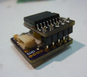
A data logger, the NT Logger, can be connected to the NT bus, which allows us to record on a micro SD card a substantial amount of data. The data are recorded for each cycle of the controller loop, i.e., with the maximal possible time resolution. The NT Logger is quite small and can be easily mounted on any vehicle. This way one can get highly accurate and informative data taken during a real flight condition. The same data can also be recorded on the ground, without the need of a NT Logger, using the live-recording feature.
The data logging option allows us to diagnose any in-flight troubles, such as jello or micro vibrations in the video, and find solutions to resolve them. It also suggests many other applications. For instance, one may use it to dynamically balance the motors and propellers.
Comment: The data logger must be a NT Logger; any other logger, such as the widely available OpenLog and its derivatives, cannot be used.
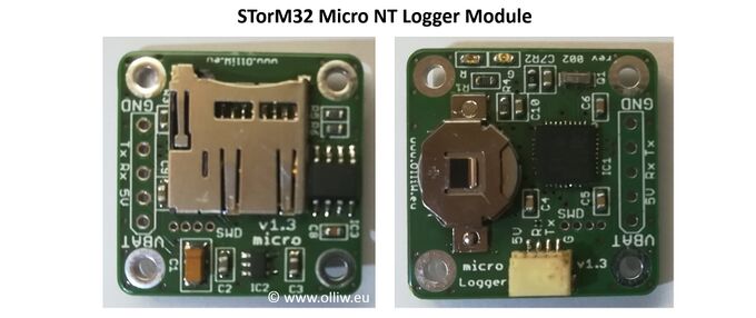
NT Logger Modules
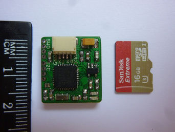
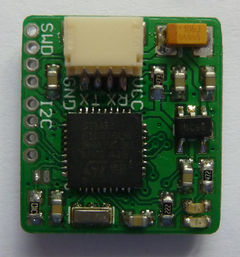
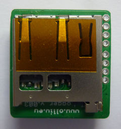
Micro NT Logger Module v1.32
The Micro NT Logger module has the RTC integrated and uses a replaceable battery cell.
NT Logger Module v1.3
This NT Logger module can be extended by connecting a RTC (real time clock) module to its I2C port. Any RTC module which is based on the DS3231 chip can be used. However, the "Raspberry Pi Mini RTC module" is most recommended, because of its low cost and tiny size. In fact, the NT Logger v1.3 PCB is designed specifically for that module.
SD Card
The micro SD card must be formatted with FAT32. The firmware author uses the Windows tool. Using the SD Association formatting tool didn't yielded any noticeable advantage.
The micro SD card should be of very high speed. Unfortunately, not any card works equally well. This experience is available:
| micro SD card | experience | reported by |
|---|---|---|
| SanDisk Extreme Micro SDHC 32GB Class 10 UHS-I UHS-Class 3 V30 A1-L (SDSQXAF-032G-GN6MA) | excellent, nearly no missing frames | OlliW |
| SanDisk Extreme Micro SDHC 16GB UHS-I Class 10 U3 | very good, missing frames of ca. 0.1% | OlliW, GekoCH |
| SanDisk Ultra Micro SDHC 16GB UHS-I Class 10 HC1 | very good, missing frames below 0.1% | OlliW |
| Kingston 8GB HC class 4 | bad, missing frames of ca. 20% | OlliW |
| Kingston 32GB HC class 4 | bad, missing frames of ca. 20% | OlliW |
RTC
The NT Logger module can be equipped with a RTC (real time clock) module to its I2C port, and the Micro NT Logger has it already on board. This makes it possible to append the data file names with a precise date&time stamp, which makes identifying the data files on the SD card much simpler. This little feature is in fact so useful, that one wouldn't want to miss it once one has used it once :).
The RTC module must be configured before it can be properly used, i.e., the current date and time must be written to it at least once. This can be conveniently done via the GUI: Go to the [GUI:Tools] menu and call the [GUI:NTLogger RTC Tool].
NTLoggerTool
For analyzing the recorded data, the NTLoggerTool is available, providing tools such as FFT, and others. The NTLoggerTool also allows us to record directly the data on the NT bus using a USB-TTL adapter; a feature called live-recording. It enables many work-bench tests and procedures.
The NTLoggerTool is steadily advancing and any manual would be quickly outdated. For a discussion it is best to join the STorM32 NT thread at rcgroups.
The NTLoggerTool is open source (GPL3). Anyone is highly welcome to contribute to it.
Logged Data
The data logger "spies" on the STorM32's NT Tx line, i.e., is capable of recording all data transmitted from the STorM32 to the NT modules. The points in the controller loop at which data are "sampled" are indicated in this sketch:
GUI Settings
The actual data which are emitted by the STorM32 controller can be fine adjusted by parameter NT Logging, found in the [GUI:Setup] window. It is a bit mask, and allows combining these options:
| NT Logging | data |
|---|---|
| “basic” | SetLogger, CmdAhrs, SetMotorAll |
| “acc & gyro raw” | CmdAccGyroRaw for Imu1 & Imu2 |
| “pid” | CmdPid |
| “acc & gyro” | CmdAccGyro for Imu1 & Imu2 |
It occasionally can happen that not all data can be transmitted in one cycle, if the computational load in that cycle is too high to support the full data rate. This essentially only occurs with both 2nd IMU and full data logging enabled. In that case the “acc & gyro” data are distributed over several cycles.
Also the data rate of the micro SD card represents an obvious limitation. If the SD card can't keep up, frames (the data of one controller cycle) will be lost. Lowering the logging can alleviate that a lot.
For vibration analysis, the experience so far shows that the “acc & gyro raw” data are most useful. It is thus recommended to have these enabled. The “pid” and “acc & gyro” data are comparatively less useful for that purpose.
Live Recording
It is also possible to "spy" on the STorM32's NT Tx line using a USB-TTL adapter, and record the data using the NTLoggerTool. The feature is somewhat analogous to the DataDisplay in the STorM32 GUI, except that it records much more data and moreover at full speed, with maximal time resolution.
The USB-TTL adapter must be capable of handling 2.000.000 bauds. Adapters with FT232RL (FTDI) work out of the box. Adapters with CP2102 may be configured to do so, see How to configure CP2102 USB adapters for high baud rates. The firmware author has much better results with a CP2102-based adapter. His FT232RL adapters appear to have problems with keeping up with the high data rate (it's about 1Mb/s), yielding many data gaps, while with a CP2102 adapter no data are lost.
The USB-TTL adapter is connected to the NT bus as follows:
USB-TTL adapter GND -> STorM32 NT GND
USB-TTL adapter Rx  -> STorM32 NT Tx
USB-TTL adapter Tx  -> do not connect
The USB-TTL adapter's Tx line must not be connected to the STorM32's NT Rx line, i.e., should be left floating.
Data Fields
Performance:
Various metrics measuring the execution time of some parts of the code.
Imu1 Pitch,Roll,Yaw:
Angles of IMU1, or the camera, respectively, as also visible in the GUI. These are the angles as they are coming out of the IMU1 AHRS and enter the PID.
Imu2 Pitch,Roll,Yaw:
Angles of the 2nd IMU (IMU2), as also visible in the GUI. These are the angles as they are coming out of the IMU2 AHRS and enter the PID and 2nd IMU calculations.
PID Pitch,Roll,Yaw:
PID controller output, as also visible in the GUI. These are the angles as they are coming out after the PID controller and enter the 2nd IMU calculations.
Ahrs1:
Various metrics related to the IMU1 AHRS.
State:
State of the controller, as also visible in the GUI. 0 = StrtMotors, 1 = Settle, 2 = Calibrate, 3 = Level, 4 = MotorDir, 5 = Relevel, 6 = Normal, 7 = FastLevel
Error:
Error counts on the NT bus, as also visible in the GUI.
Voltage:
Battery voltage, as also visible in the GUI.
Acc1, Gyro1:
Accelerometer and gyroscope measurements of IMU1. These are the data as they are coming out after the calibration, bias, filter, and orientation corrections, and enter the IMU1 AHRS.
Acc2, Gyro2:
Accelerometer and gyroscope measurements of IMU2. These are the data as they are coming out after the calibration, bias, and orientation corrections, and enter the IMU2 AHRS.
Acc1 raw, Gyro1 raw:
These are the raw accelerometer and gyroscope data, as they are coming out of IMU1, before any other processing. Note that therefore the x,y,z axes refer to the orientation of the IMU1 chip, and not the STorM32's x,y,z axes from which the angles are derived, as the orientation correction has not been passed by these data.
Acc2 raw, Gyro2 raw:
These are the raw accelerometer and gyroscope data, as they are coming out of IMU2, before any other processing. Note that therefore the x,y,z axes refer to the orientation of the IMU2 chip, and not the STorM32's x,y,z axes from which the angles are derived, as the orientation correction has not been passed by these data.
Acc3 raw, Gyro3 raw:
These are the raw accelerometer and gyroscope data, as they are coming out of IMU3, before any other processing. Note that therefore the x,y,z axes refer to the orientation of the IMU3 chip, and not the STorM32's x,y,z axes from which the angles are derived, as these data have not passed any orientation correction.
Temp 1+2+3:
Temperature of IMU1, IMU2, IMU3
PID Mot Pitch,Roll,Yaw:
Motor angles as they are coming out after the 2nd IMU calculations, and enter the motor drivers.
PID Mot Pitch,Roll,Yaw:
Motor angles as they are send to the motor drivers.
Vmax Pitch,Roll,Yaw:
Vmax for each motor axis.
