Leds: Difference between revisions
No edit summary |
No edit summary |
||
| Line 1: | Line 1: | ||
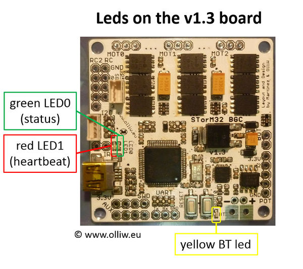
The STorM32 | The STorM32 board has two LEDs, a green LED named LED0 and a red LED named LED1, which provide info about the controller's current condition. There is also a third yellow LED, which however is related to the HC06 Bluetooth module. | ||
== Red Led (LED1) == | == Red Led (LED1) == | ||
The red LED1 is so to say a heartbeat, it should blink at a frequency of about 1 | The red LED1 is so to say a heartbeat, it should blink at a frequency of about 1 Hz in normal operation. In case of an error condition, such as a low battery voltage or missing IMU, it blinks however much faster (which is accompanied by a fast blinking of the green LED). | ||
== Green Led (LED0) == | == Green Led (LED0) == | ||
The green LED0 tells about the current state of the controller, e.g. at startup it undergoes a sequence of ever faster blink sequences. When the | The green LED0 tells about the current state of the controller, e.g. at startup it undergoes a sequence of ever faster blink sequences. When the NORMAL state is reached the green LED is permanently on. For more details see [[Getting_Started#First_Startup|Getting Started: First Startup]]. | ||
== Yellow Led == | == Yellow Led == | ||
This | This LED is directly connected with the HC06 Bluetooth module. Hence, it doesn't tell anything about the working of the STorM32 board, its meaning has to be read off from the documentation for the HC06 module (see [http://www.olliw.eu/storm32bgc-wiki/index.php5/Bluetooth_Module_HC06#Technical_Documentation here]). | ||
The permanent blinking of this | The permanent blinking of this LED may be annoying, and one might wish to deactivate it (on v1.3 boards scratch through the solder jumper on the bottom, otherwise desolder the respective resistor). | ||
[[File:Stom32-bgc-v130-leds-01.jpg|600px]] | [[File:Stom32-bgc-v130-leds-01.jpg|600px]] | ||
Revision as of 19:00, 2 July 2016
The STorM32 board has two LEDs, a green LED named LED0 and a red LED named LED1, which provide info about the controller's current condition. There is also a third yellow LED, which however is related to the HC06 Bluetooth module.
Red Led (LED1)
The red LED1 is so to say a heartbeat, it should blink at a frequency of about 1 Hz in normal operation. In case of an error condition, such as a low battery voltage or missing IMU, it blinks however much faster (which is accompanied by a fast blinking of the green LED).
Green Led (LED0)
The green LED0 tells about the current state of the controller, e.g. at startup it undergoes a sequence of ever faster blink sequences. When the NORMAL state is reached the green LED is permanently on. For more details see Getting Started: First Startup.
Yellow Led
This LED is directly connected with the HC06 Bluetooth module. Hence, it doesn't tell anything about the working of the STorM32 board, its meaning has to be read off from the documentation for the HC06 module (see here).
The permanent blinking of this LED may be annoying, and one might wish to deactivate it (on v1.3 boards scratch through the solder jumper on the bottom, otherwise desolder the respective resistor).
