STorM32 Boards: Difference between revisions
Jump to navigation
Jump to search
No edit summary |
No edit summary |
||
| Line 27: | Line 27: | ||
| | | | ||
* supply voltage: 6 - 18 V or 2 - 4S | * supply voltage: 6 - 18 V or 2 - 4S | ||
* motor current: max. 1.5 A per motor<br/> | * motor current: max. 1.5 A per motor<br/>'''''Comment''': This is not yet fully exploited, motors with resistances of 12 Ohm or larger have been tested to be well handled at 4S (see [//www.rcgroups.com/forums/showthread.php?t=2055844&page=2&pp=50#post27515444 here], [//www.rcgroups.com/forums/showthread.php?t=2055844&page=15&pp=50#post28578479 here]), motors with 10 Ohm may be handled with care (see [http://www.rcgroups.com/forums/showpost.php?p=28825482&postcount=947 here] and [http://www.rcgroups.com/forums/showpost.php?p=28852888&postcount=953 here])''. | ||
* board dimensions: 50 mm x 50 mm, 45 mm bolt to bolt, holes Ø3 mm | |||
* board dimensions: 50 mm x 50 mm, 45 mm bolt to bolt, holes Ø3 mm | * board dimensions: 50 mm x 50 mm, 45 mm bolt to bolt, holes Ø3 mm | ||
|} | |} | ||
Revision as of 11:25, 13 July 2014
At present, three different versions of STorM32-BGC boards are in use (v0.17/v1.0 boards are deprecated).
Comments:
- The boards can be populated with different motor drivers: the TC4452 driver in DFN package or the TC4452 driver in SOIC package; the DFN package allows somewhat higher motor currents.
- The boards can in principle be populated with different microcontrollers; the standard configuration is a STM32F103RC.
- For a detailed description of the various connectors on the board see Pins and Connectors.
- To avoid confusion/misunderstandings please note: The boards provide many features hardware-wise, but not all are yet supported by the firmware.
STorM32-BGC v1.3
|
|
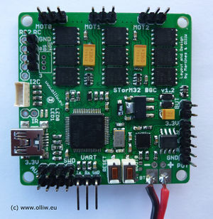
STorM32-BGC v1.2
Differences to the v1.3 board:
- voltage regulator: smaller SOT223 package
- only 2 auxiliary ports
STorM32-BGC v1.1
Differences to the v1.2 board:
- no Futaba S-bus support
- Spektrum satellite is supported, but no extra Spektrum connector on board
- no extra USB voltage protection diode
- voltage regulator: smaller SOT223 package
- only 2 auxiliary ports
Comment: The order of pins on the I2C#2 port is reversed to that on the I2C#1 port; please consider this then connecting an MPU module to the I2C#2 port. Note that this does not apply to the witespy board; here the issue has been resolved by a smart plug.


