|
|
| Line 11: |
Line 11: |
| In addition to the boards shown here, also other variants exist, such as e.g. micro versions. | | In addition to the boards shown here, also other variants exist, such as e.g. micro versions. |
|
| |
|
| The design schemes are provided in https://github.com/olliw42/storm32bgc | | The design schemes are located in https://github.com/olliw42/storm32bgc |
|
| |
|
| === STorM32-BGC v6.2 === | | === STorM32-BGC v6.2 === |
"Original" STorM32 Boards
At present, board versions v3.3, v4.1 and v6.2 are supported (v0.17/v1.0, v1.1, v1.2, v1.3x, v2.4 boards are deprecated).
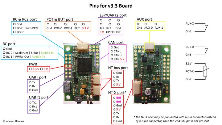
The STorM32 boards offer two types of NT bus ports, the NT and NT-X ports. They both are different from the NT bus connectors on the NT modules in that they have swapped Rx, Tx pins.
Comment: The Rx, Tx pins of the NT and NT-X ports on the STorM32 board must be connected to the Tx, Rx pins on the NT modules.
Comment: The v3.3 and v6.2 STorM32 boards have no motor drivers on-board, i.e., NT motor modules are needed in addition.
In addition to the boards shown here, also other variants exist, such as e.g. micro versions.
The design schemes are located in https://github.com/olliw42/storm32bgc
STorM32-BGC v6.2
- MCU: STM32H7A3RG at 280 MHz
- motor drivers: none
- voltage regulator: 5 V, 2.0 A low-noise switching regulator
- on-board IMU: ICM42688P/ICM42688V
- 2x NT port and 1x NT-X port
- USB-C connector, permits flashing per USB (DFU)
- UART2/ESP port
- CRSF, Futaba S-Bus
- up to four PWM/Sum-PPM inputs/outputs
- joystick port (ADC) for two axes
- 2 auxiliary ports (digital), BUT port
|
- supply voltage: 6 - 27 V or 2 - 6S
- motor current: depends on used NT motor modules
- board dimensions: 40 mm x 25 mm, 35 mm bolt to bolt, holes Ø3 mm
|
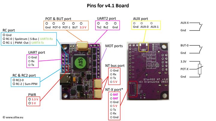
STorM32-BGC v4.1
- MCU: STM32F103RC at 72 MHz
- motor drivers: DRV8839
- voltage regulator: 5 V, 2 A (??) switching regulator
- on-board IMU: ICM42688P/ICM42688V
- 2x NT port and 1x NT-X port
- on-board USB-TTL adapter CP2102, permits flashing per USB
- USB-C connector
- UART2/ESP port
- CRSF, Futaba S-Bus
- up to four PWM/Sum-PPM inputs/outputs
- joystick port (ADC) for two axes
- 2 auxiliary ports (digital), BUT port
|
- supply voltage:
with motor drivers enabled: 6 - 12 V or 2 - 3S
with motor drivers disabled: 6 - 20 V or 2 - 4S
Comment: The motor drivers are enabled by closing the JP1 solder bridge.
- motor current: 1.0 A (??)
- board dimensions: 40 mm x 28 mm, 35 mm bolt to bolt, holes Ø3 mm
|
Comment: This board is design of KrattWorks, [1].
STorM32-BGC v3.3m, v3.3i
- MCU: STM32F103RC at 72 MHz
- motor drivers: none
- voltage regulator: 5 V, 0.6 A low-noise switching regulator
- on-board IMU: ICM42605/ICM42688P/ICM42688V (v3.3i), or MPU9250 (v3.3m)
- 2x NT port and 1x NT-X port
- on-board USB-TTL adapter CP2102, permits flashing per USB
- UART2/ESP port
- CRSF, Futaba S-Bus
- up to four PWM/Sum-PPM inputs/outputs
- joystick port (ADC) for two axes
- 2 auxiliary ports (digital), BUT port
- CAN bus port (obsolete, not supported anymore)
|
- supply voltage: 6 - 27 V or 2 - 6S
- motor current: depends on used NT motor modules
- board dimensions: 40 mm x 25 mm, 35 mm bolt to bolt, holes Ø3 mm
|
Comment: Tthe v3.3i version has a ICM42605/ICM42688P/ICM42688V on-board IMU, the v3.3m version has a MPU9250 on-board IMU.
Comment: This board has no motor drivers; NT motor modules are thus mandatorily required.