STorM32 Boards: Difference between revisions
Jump to navigation
Jump to search
No edit summary |
No edit summary |
||
| Line 4: | Line 4: | ||
Comments: | Comments: | ||
* The boards can in principle be populated with different microcontrollers; below the "typical" configuration is mentioned. | * The boards can in principle be populated with different microcontrollers; below the "typical" configuration is mentioned. | ||
* To avoid confusion/missunderstandings please note: The | * To avoid confusion/missunderstandings please note: The boards provide many features hardware-wise, but not all are however currently supported by the firmware. | ||
| Line 12: | Line 12: | ||
* MCU: STM32F103RC | * MCU: STM32F103RC | ||
* Motor drivers: TC4452VMF | |||
* on-board Bluetooth (optional) | |||
* on-board 6DOF IMU (MPU6050) | |||
* IR led | * IR led | ||
* Futaba S-Bus | * Futaba S-Bus | ||
* Spektrum Satellite | * Spektrum Satellite | ||
* up to seven PWM/Sum-PPM inputs/outputs | |||
* joystick for each axis | * joystick for each axis | ||
* | * additional I2C port (I2C#2) | ||
* 2 auxiliary ports | |||
* BUT port | |||
Revision as of 19:56, 20 February 2014
At present, three different versions of STorM32-BGC boards are around.
Comments:
- The boards can in principle be populated with different microcontrollers; below the "typical" configuration is mentioned.
- To avoid confusion/missunderstandings please note: The boards provide many features hardware-wise, but not all are however currently supported by the firmware.
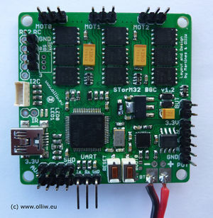
STorM32-BGC v1.2
- MCU: STM32F103RC
- Motor drivers: TC4452VMF
- on-board Bluetooth (optional)
- on-board 6DOF IMU (MPU6050)
- IR led
- Futaba S-Bus
- Spektrum Satellite
- up to seven PWM/Sum-PPM inputs/outputs
- joystick for each axis
- additional I2C port (I2C#2)
- 2 auxiliary ports
- BUT port
STorM32-BGC v1.1
- MCU: STM32F103RC
Comments:
- The order of pins on the I2C#2 port is reversed to that on the I2C#1 port; please consider this then connecting an MPU module to this port.
STorM32-BGC v0.17/v1.0
- MCU: STM32F103RB
Comments:
- The location of the pins needed to flash the firmware via an USB-TTL adapter is different here. Namely:
- RC-GND = GND -> connect it to GND on the usb-ttl adapter
- RC-1 = Uart1-Tx -> connect it to Rx on the usb-ttl adapter
- RC-2 = Uart1-Rx -> connect it to Tx on the usb-ttl adapter
