Using a OLED Display: Difference between revisions
(→Setup) |
No edit summary |
||
| (23 intermediate revisions by the same user not shown) | |||
| Line 1: | Line 1: | ||
''The information on this page refers to firmware v2.31e and higher.'' | ''The information on this page refers to firmware v2.31e and higher. The feature got removed with firmware v2.61.'' | ||
Since firmware version v2.31e, the STorM32 supports OLED displays. It allows to graphically present various information, such as the battery voltage and charge level, the gimbal status, and the currently selected pan mode. | Since firmware version v2.31e, the STorM32 supports OLED displays. It allows to graphically present various information, such as the battery voltage and charge level, the gimbal status, and the currently selected pan mode. | ||
| Line 5: | Line 5: | ||
{{#ev:youtube|mso4yRp5ymc|480}} | {{#ev:youtube|mso4yRp5ymc|480}} | ||
Unfortunately, the OLED display cannot be directly connected to the STorM32 main board. This is so because otherwise only v3.x boards could have been supported, but not the abundant v1.x boards. Also, the firmware is | Unfortunately, the OLED display cannot be directly connected to the STorM32 main board. This is so because otherwise only v3.x boards could have been supported, but not the abundant v1.x boards. Also, the STorM32 firmware is exhausting the resources of the F103RC micro-controller, and supporting the OLED display in addition would compromise features. Thus, the STorM32's OLED support involves a bridge module, which is connected in between the STorM32 and the OLED display. On the positive side, this approach potentially allows users to customize the displayed information to their specific needs. | ||
Currently, firmware is provided | Currently, firmware is provided for bridge modules which use a STM32 F103T8, F103C8, or F103CB chip. This covers many of the available STM32 development boards, as well as the CC3D atom. | ||
'''''Call for contribution:''' A 32-bit micro-controller is not required; 8-bit controllers such as the ATmega | '''''Call for contribution:''' A 32-bit micro-controller is not required; 8-bit controllers such as the ATmega would be fine too. That is, it would be possible to create a OLED bridge module using an Arduino. The firmware author has no intent to do that himself, but would strongly support any effort in this direction. E.g., if, someone would identify suitable hardware and establish a basic Arduino code, which implements an UART at 115200 baud and the OLED drivers (e.g. using the [[https://learn.adafruit.com/adafruit-gfx-graphics-library/overview AdafruitGFX]] library), then the firmware author would be happy to add the communication code to make it functional.'' | ||
<div class="toclimit-2">__TOC__</div> | <div class="toclimit-2">__TOC__</div> | ||
== | == Ordering Information == | ||
Things to have at minimum: | Things to have at minimum: | ||
* 128x64 OLED display with SSD1306 controller and I2C | * 128x64 OLED display with SSD1306 controller and I2C | ||
* STM32 module with F103T8, F103C8, or F103CB micro-controller | * STM32 module with F103T8, F103C8, or F103CB micro-controller, e.g. a Display v1.3 PCB | ||
* something to flash the micro-controller (USB-TTL adapter or ST-Link) | * something to flash the micro-controller (USB-TTL adapter or ST-Link) | ||
The OLED display is available for few bucks at many places. However, a large variety exist, with different display controllers (SSD1306, SH1106, ...), different sizes (0.96 | The OLED display is available for few bucks at many places. However, a large variety exist, with different display controllers (SSD1306, SH1106, ...), different sizes (0.96", 1.3", ...), different resolution (128x64, 128x32,...), and different pins (I2C, SPI, I2C&SPI, ...). It is important to get a suitable OLED module; the specs are given in the list. | ||
In addition a module with a | In addition a STM32 module with a F103T8, F103C8, or F103CB micro-controller is required. This can be anything available which provides access to the UART1, I2C pins, and the programming pins (BOOT0, or SWDCLK, SWDIO). Many development boards exist at low cost; they are however relatively bulky. Also the CC3D atom can be used, which is potentially the smallest commercially available option. Lastly, also the OLED Display v1.3 print board is available, which is specifically designed for the purpose (https://github.com/olliw42/storm32bgc/tree/master/storm32-nt/storm32-nt-display-v13). | ||
Finally the hardware for flashing the STM32 micro-controller is required, usually a USB-TTL adapter or a ST-Link, depending on the STM32 module. This article [[How_to_flash_NT_Modules#First-Time_Flashing|How to flash NT Modules: First-Time Flashing]] provides information. | Finally the hardware for flashing the STM32 micro-controller is required, usually a USB-TTL adapter or a ST-Link, depending on the STM32 module. This article [[How_to_flash_NT_Modules#First-Time_Flashing|How to flash NT Modules: First-Time Flashing]] provides information. | ||
:[[File: | :[[File:Oled-display-module-v13.jpg|680px]] | ||
== Firmware == | == Firmware == | ||
The firmware | The firmware can be accessed and flashed using the GUI. The usual flashing procedures are available, and are distinguished into '''''upgrading''''' and '''''first time flashing''''', depending on whether a previous firmware is already installed on the OLED module or not. The procedures are analogous to those for flashing v3.3 STorM32 boards or NT modules, and thus not repeated here. Please consult [[How to flash NT Modules]] as references. | ||
For upgrading the firmware the settings in GUI would look similar to this: | |||
:[[File:Oled-upgrading.jpg|480px]] | |||
== Setup == | == Setup == | ||
:[[File:Oled-gui-configuration.jpg]] | The connections are as follows: | ||
:[[File:Oled-scheme.jpg|680px]] | |||
The I2C pins SCL, SDA of the OLED display need to be connected to either the I2C1 or I2C2 pins of STM32 micro-controller (the firmware auto-detects which I2C unit is being used). On the other side the Rx and Tx pins of UART1 need to be connected to the RC1 and RC0 pins on the RC port of the STorM32 controller. | |||
On the CC3D atom, for instance, these can be accessed: | |||
* I2C1 (SCL = PB6, SDA = PB7): pin S1out goes to SCL, and pin S3out goes to SDA | |||
* I2C2 (SCL = PB10, SDA = PB11): they are found on the Flexi port, pin 3 = Tx goes to SCL, and pin 4 = Rx goes to SDA | |||
* UART1-Rx (Rx = PA10): is found on the Main port, pin 4 = Rx goes to RC1 | |||
* UART1-Tx (Rx = PA9): is found on the Main port, pin 3 = Tx goes to RC0 | |||
The powering of the OLED is relatively uncritical, it can be powered by both a 3.3 V or a 5 V source. It draws ca. 20 mA. The 3.3 V pin on the v1.31 STorM32 board might be too weak, the 3.3 V on the v1.3 STorM32 board should be fine (depending on what else is connected of course). | |||
Finally, the OLED display support needs to be enabled in the GUI by setting {{PARAMNAME|Uart1 Tx Configuration}} to {{PARAMVALUE|oled display}}. | |||
:[[File:Storm32-wiki-oled-gui-configuration-1.jpg|480px]] | |||
Latest revision as of 06:57, 22 July 2022
The information on this page refers to firmware v2.31e and higher. The feature got removed with firmware v2.61.
Since firmware version v2.31e, the STorM32 supports OLED displays. It allows to graphically present various information, such as the battery voltage and charge level, the gimbal status, and the currently selected pan mode.
Unfortunately, the OLED display cannot be directly connected to the STorM32 main board. This is so because otherwise only v3.x boards could have been supported, but not the abundant v1.x boards. Also, the STorM32 firmware is exhausting the resources of the F103RC micro-controller, and supporting the OLED display in addition would compromise features. Thus, the STorM32's OLED support involves a bridge module, which is connected in between the STorM32 and the OLED display. On the positive side, this approach potentially allows users to customize the displayed information to their specific needs.
Currently, firmware is provided for bridge modules which use a STM32 F103T8, F103C8, or F103CB chip. This covers many of the available STM32 development boards, as well as the CC3D atom.
Call for contribution: A 32-bit micro-controller is not required; 8-bit controllers such as the ATmega would be fine too. That is, it would be possible to create a OLED bridge module using an Arduino. The firmware author has no intent to do that himself, but would strongly support any effort in this direction. E.g., if, someone would identify suitable hardware and establish a basic Arduino code, which implements an UART at 115200 baud and the OLED drivers (e.g. using the [AdafruitGFX] library), then the firmware author would be happy to add the communication code to make it functional.
Ordering Information
Things to have at minimum:
- 128x64 OLED display with SSD1306 controller and I2C
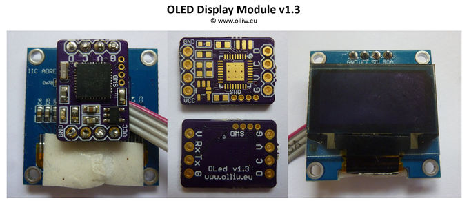
- STM32 module with F103T8, F103C8, or F103CB micro-controller, e.g. a Display v1.3 PCB
- something to flash the micro-controller (USB-TTL adapter or ST-Link)
The OLED display is available for few bucks at many places. However, a large variety exist, with different display controllers (SSD1306, SH1106, ...), different sizes (0.96", 1.3", ...), different resolution (128x64, 128x32,...), and different pins (I2C, SPI, I2C&SPI, ...). It is important to get a suitable OLED module; the specs are given in the list.
In addition a STM32 module with a F103T8, F103C8, or F103CB micro-controller is required. This can be anything available which provides access to the UART1, I2C pins, and the programming pins (BOOT0, or SWDCLK, SWDIO). Many development boards exist at low cost; they are however relatively bulky. Also the CC3D atom can be used, which is potentially the smallest commercially available option. Lastly, also the OLED Display v1.3 print board is available, which is specifically designed for the purpose (https://github.com/olliw42/storm32bgc/tree/master/storm32-nt/storm32-nt-display-v13).
Finally the hardware for flashing the STM32 micro-controller is required, usually a USB-TTL adapter or a ST-Link, depending on the STM32 module. This article How to flash NT Modules: First-Time Flashing provides information.
Firmware
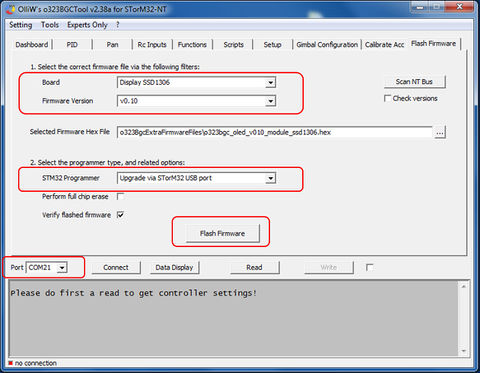
The firmware can be accessed and flashed using the GUI. The usual flashing procedures are available, and are distinguished into upgrading and first time flashing, depending on whether a previous firmware is already installed on the OLED module or not. The procedures are analogous to those for flashing v3.3 STorM32 boards or NT modules, and thus not repeated here. Please consult How to flash NT Modules as references.
For upgrading the firmware the settings in GUI would look similar to this:
Setup
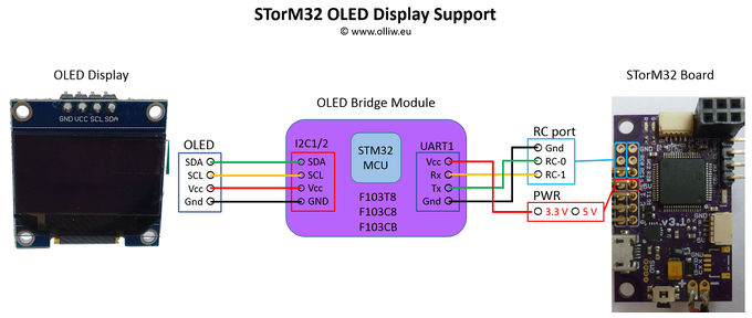
The connections are as follows:
The I2C pins SCL, SDA of the OLED display need to be connected to either the I2C1 or I2C2 pins of STM32 micro-controller (the firmware auto-detects which I2C unit is being used). On the other side the Rx and Tx pins of UART1 need to be connected to the RC1 and RC0 pins on the RC port of the STorM32 controller.
On the CC3D atom, for instance, these can be accessed:
- I2C1 (SCL = PB6, SDA = PB7): pin S1out goes to SCL, and pin S3out goes to SDA
- I2C2 (SCL = PB10, SDA = PB11): they are found on the Flexi port, pin 3 = Tx goes to SCL, and pin 4 = Rx goes to SDA
- UART1-Rx (Rx = PA10): is found on the Main port, pin 4 = Rx goes to RC1
- UART1-Tx (Rx = PA9): is found on the Main port, pin 3 = Tx goes to RC0
The powering of the OLED is relatively uncritical, it can be powered by both a 3.3 V or a 5 V source. It draws ca. 20 mA. The 3.3 V pin on the v1.31 STorM32 board might be too weak, the 3.3 V on the v1.3 STorM32 board should be fine (depending on what else is connected of course).
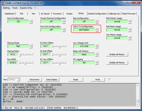
Finally, the OLED display support needs to be enabled in the GUI by setting Uart1 Tx Configuration to “oled display”.


