Getting Started with T-STorM32: Difference between revisions
(Created page with "This is a first attempt of a documentation for the T-STorM32. Will be relatively disorganized at first.") |
No edit summary |
||
| Line 1: | Line 1: | ||
This is a first attempt of a documentation for the T-STorM32. Will be relatively disorganized at first. | This is a first attempt of a documentation for the T-STorM32. Will be relatively disorganized at first. | ||
== Concept == | |||
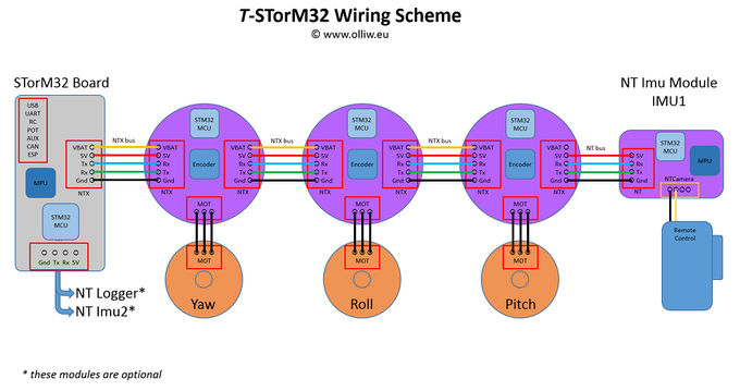
The encoder support builds on the NT concept, and especially on the possibility of connecting separated NT motor modules to the NT bus. For T-STorM32 you need, in addition to the main controller board, three NT motor modules which include the encoders. These shall be called NT motor-encoder modules (or should we choose to call them TNT motor modules ? :)). | |||
The motor drivers on the main STorM32 board cannot be used, and unlike Basecam/Alexmos, it is also not possible to connect encoders to the main STorM32 board. One needs three NT motor-encoder modules, one for each axis, connected to the NT bus, and battery power. | |||
The concept, also sketching a typical wiring scheme, thus looks as this: | |||
:[[File:Tstorm32-wiring-scheme-sketch.jpg|none|680px|center]] | |||
Revision as of 10:40, 14 March 2017
This is a first attempt of a documentation for the T-STorM32. Will be relatively disorganized at first.
Concept
The encoder support builds on the NT concept, and especially on the possibility of connecting separated NT motor modules to the NT bus. For T-STorM32 you need, in addition to the main controller board, three NT motor modules which include the encoders. These shall be called NT motor-encoder modules (or should we choose to call them TNT motor modules ? :)).
The motor drivers on the main STorM32 board cannot be used, and unlike Basecam/Alexmos, it is also not possible to connect encoders to the main STorM32 board. One needs three NT motor-encoder modules, one for each axis, connected to the NT bus, and battery power.
The concept, also sketching a typical wiring scheme, thus looks as this:
