Evaluating Vibrations and Optimizing Damper Systems: Difference between revisions
| Line 4: | Line 4: | ||
== Conceptional == | == Conceptional == | ||
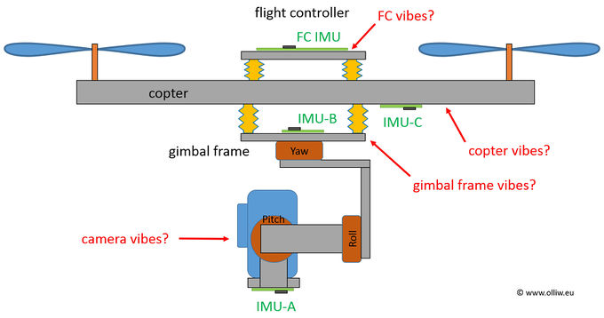
The basic idea of the STorM32's vibration and damping system analysis is sketched in the following picture. | |||
::[[File:Storm32-nt-vibrations-overview-01.jpg|680px]] | ::[[File:Storm32-nt-vibrations-overview-01.jpg|680px]] | ||
{{#ev:youtube|nGp_PlPxleQ|480}} | Usually, the flight controller is used for analyzing the copter's vibrations, and most UAV codes provide features to do so. However, the disadvantage is immediately obvious from the picture, namely that in most cases the flight controller doesn't "see" the real vibrations of the copter, since it is mounted with some dampers. What really matters are the vibrations at the camera, which is obviously is "far away" from the flight controller. That is, in a technical language, the transfer functions for the copter's vibrations to the flight controller and the camera are substantially different. For a proper - and complete - analysis of the relevant vibrations one needs to know the vibrations on the copter, on the gimbal frame, and the camera. It is pointed out, that only with knowing the vibrations on the copter '''''and''''' the gimbal frame the performance of the gimbal damping system can actually be assessed. | ||
That's the basic idea of the StorM32's three IMU setup, to provide us with a means to properly evaluate the vibrations and especially gimbal damping system, which hopefully will allow us to develop better gimbals. | |||
It is stressed though that the offered mechanisms can be used also in other ways, e.g. for balancing motors and propellers. That's only up to our creativity. | |||
{{COMMENT|In order to avoid confusion, this clarification: In the above sketch the IMU on the gimbal frame is named IMU2 and that on the copter IMU3. However, depending on the user's setup it could be also vice versa. That is because the 2nd IMU (in the terminology of the STorM32 gimbal controller) can be either located on the gimbal frame or the copter, and it is this 2nd IMU which is called IMU2.}} | |||
The following video explains that too, and also shows possible uses of the NTLoggerTool and Blackbox Explorer. | |||
::::::{{#ev:youtube|nGp_PlPxleQ|480}} | |||
== NT Logger == | == NT Logger == | ||
Revision as of 10:48, 27 March 2016
For aerial video applications, one of the most difficult aspects of a DIY gimbal system is to achieve a low level of vibrations and a well working damping system. The first reaction of most users to artefacts such as micro vibs or jello in the video seems to be to resort to PID tuning, while in fact the secret sauce of a well working system usually lies not in the PID tuning, which generally is "simple", but the copter vibration level and construction of the gimbal damping system.
Unfortunately, when it comes to the latter aspects the current approach available to us DIY guys is essentially trial-and-error, which at times can be frustrating. The STorM32 NT thus aims at providing tools to alleviate the situation. This is still an effort in progress, meaning that the best set of tools and/or best set of recipes to achieve the goals have not yet been established. However, some tools and procedures have emerged.
Conceptional
The basic idea of the STorM32's vibration and damping system analysis is sketched in the following picture.
Usually, the flight controller is used for analyzing the copter's vibrations, and most UAV codes provide features to do so. However, the disadvantage is immediately obvious from the picture, namely that in most cases the flight controller doesn't "see" the real vibrations of the copter, since it is mounted with some dampers. What really matters are the vibrations at the camera, which is obviously is "far away" from the flight controller. That is, in a technical language, the transfer functions for the copter's vibrations to the flight controller and the camera are substantially different. For a proper - and complete - analysis of the relevant vibrations one needs to know the vibrations on the copter, on the gimbal frame, and the camera. It is pointed out, that only with knowing the vibrations on the copter and the gimbal frame the performance of the gimbal damping system can actually be assessed.
That's the basic idea of the StorM32's three IMU setup, to provide us with a means to properly evaluate the vibrations and especially gimbal damping system, which hopefully will allow us to develop better gimbals.
It is stressed though that the offered mechanisms can be used also in other ways, e.g. for balancing motors and propellers. That's only up to our creativity.
Comment: In order to avoid confusion, this clarification: In the above sketch the IMU on the gimbal frame is named IMU2 and that on the copter IMU3. However, depending on the user's setup it could be also vice versa. That is because the 2nd IMU (in the terminology of the STorM32 gimbal controller) can be either located on the gimbal frame or the copter, and it is this 2nd IMU which is called IMU2.
The following video explains that too, and also shows possible uses of the NTLoggerTool and Blackbox Explorer.
