How to flash firmware: Difference between revisions
No edit summary |
No edit summary |
||
| (150 intermediate revisions by 8 users not shown) | |||
| Line 1: | Line 1: | ||
This page is for instructions on how to flash firmware into {{WARNING|'''''v3.x'''''}} and {{WARNING|'''''v4.x'''''}} STorM32 boards. | |||
For instructions on how to flash {{WARNING|'''''v1.3x'''''}} STorM32 boards, please consult the article [[How to flash v1.x STorM32 boards]]. | |||
For the v3.x/v4.x boards two situations can be distinguished: | |||
''' | * '''''Upgrading''''': If your v3.x/v4.x board already runs a valid STorM32 firmware which you want to upgrade (or downgrade), then this is the recommended procedure to choose, since it is most simple. Go to [[#Updating Firmware|Updating Firmware]]. | ||
''' | * '''''First-time flashing''''': In all other cases, when your v3.x/v4.x board has not yet a STorM32 firmware installed or you don't want to use the upgrade method, this is what needs to be done. Go to [[#First-Time Flashing|First-Time Flashing]]. | ||
{{COMMENT|The same distinction also exists for flashing NT modules, see [[How to flash NT Modules]].}} | |||
__TOC__ | |||
== Updating Firmware == | |||
If your v3.x/v4.x STorM32 board runs already a firmware, then this is the canonical procedure for upgrading: | |||
''' | '''1.''' Connect the STorM32 board via its USB port to the PC. | ||
''' | :{{COMMENT|If this is the first time the board is connected via USB to the PC, then Win will immediately start with installing the appropriate USB driver. This takes quite a while (several minutes). Please, be patient and wait until Win reports that the device is ready for use. {{WARNING|'''Do not interrupt the driver installation process before it is completed'''}}. Otherwise things can get messed up quite considerably, and installing the driver later can be a challenge.}} | ||
''' | '''2.''' Run the GUI and go to the {{GUI|Flash Firmware}} tab (see the screenshot). | ||
:{{COMMENT|In principle you can use any GUI version to flash any version of the firmware. However, a GUI which is of the same or higher version than the firmware which is to be installed provides easy access to the firmware via the selector fields on the {{GUI|Flash Firmware}} window.}} | |||
::[[File:Storm32-wiki-upgrade-firmware-v3x.jpg|640px]] | |||
''' | '''3.''' In the combo boxes {{GUIFIELD|Board}} and {{GUIFIELD|Firmware Version}} select the correct board and desired firmware version. | ||
''' | :{{COMMENT|With these two selectors the correct firmware .hex file is chosen in the {{GUIFIELD|Selected Firmware Hex File}} field.}}<br/> | ||
:{{COMMENT|It is {{WARNING|'''important'''}} to choose the correct board version; otherwise you will flash a wrong firmware and the board will not functions correctly.}} | |||
''' | '''4.''' In the {{GUIFIELD|STM32 Programmer}} field select {{GUIPARAM|Upgrade via STorM32 USB port}}. | ||
''' | '''5.''' In the {{GUIFIELD|Port}} field select the COM port which your STorM32 board is connected to (it's the same port you choose when connecting to the GUI). | ||
:{{COMMENT|If you are not sure which the correct COM port is, then disconnect the STorM32 board from the PC, inspect the drop-down list and memorize the available COM ports, reconnect the STorM32 board and wait until it is enumerated by Win, inspect the drop-down list again, and chose the newly added COM port.}} | |||
'''6.''' If required or desired check the {{GUIFIELD|Perform full chip erase}} check button. | |||
'''7.''' Remind you about the upgrading process by reading the usage information. | |||
'''8.''' Finally, hit the {{GUIFIELD|Flash Firmware}} button. | |||
'''9.''' Now a black window (DOS console) should open and run the STM32CubeProgrammer flash program, as shown in the screenshot. Wait until it is finished (takes some seconds). The STorM32 board will be reset and start running. | |||
::[[File:Storm32-wiki-flash-firmware-dosbox.jpg|640px]] | |||
* | |||
* | ==== Trouble Shooting ==== | ||
* The STorM32 board has no power: Connect the board to the computer via USB to power it. | |||
* Wrong serial port is selected in the tool. | |||
* The black DOS box does not show up: Typically this happens because the firmware .zip file was not extracted. | |||
* The black DOS box shows up, displaying a [OK] and [KO] together with an error message "No response from target, the bootloader cannot be started": The error message is correct, the bootloader could not be started, because e.g. a wrong COM port was selected, the STorM32 board wasn't put into bootloader mode, the connections are incorrect, and so on. | |||
* The above steps run and the black DOS box shows the first two [OK] messages, but the downloading and verifying message lines are not be present and a firmware is not flashed: Go to [http://www.olliw.eu/storm32bgc-v1-wiki/How_to_flash_firmware#Removing_Read.26Write_Protections Removing Read&Write Protections]. | |||
* The verify fails: First double-check that you are not using an outdated GUI version. Otherwise, click the {{GUIFIELD|Perform full chip erase}} check button and repeat. Note: This will also erase any setting; if needed save the settings to a file beforehand using the option in the "Setting" menu. | |||
* The USB is not working: Please double-check that you've selected the correct board version in the {{GUIFIELD|STorM32-BGC board}} field. | |||
* In case of troubles with the USB driver, consult the [[STorM32_FAQ#Which_drivers_are_needed_for_the_USB.3F|FAQ: Which drivers are needed for the USB?]]. | |||
* On Win XP flashing via the GUI using the USB-TTL adapter will fail. See the section [[#Flashing Procedure for Win XP|Flashing Procedure for Win XP]]. | |||
* In order to test if the USB-TTL adapter is working properly, one can connect its Rx and Tx pins with each other, and use a terminal program, such as HTerm. When you send characters they should be immediately received. | |||
== First-Time Flashing == | |||
If your v3.x/v4.x STorM32 board has not yet been flashed with a STorM32 firmware, or runs a different firmware, then one needs to resort to grass roots flashing methods for flashing the firmware (first-time flashing). | |||
In general, the STM32 micro-controllers which are used in the STorM32 boards provide two different built-in methods for flashing firmware: | |||
# via the serial system bootloader using a USB-TTL adapter | |||
# via SWD using a ST-Link programmer | |||
For v3.x/v4.x boards method 1. is relatively convenient, since these boards have the USB-TTL adapter integrated and thus no additional hardware is needed for doing this. However, the grain of salt is that the BOOT0 pin needs to be temporarily shortened to GND by closing the solder jumper. | |||
Method 2. requires a dedicated ST-Link programmer device. These are cheaply available, but nevertheless it is an additional piece of hardware, which one needs. | |||
=== Flashing via System Bootloader === | |||
'''1.''' '''''Important''''': Find the BOOT0 solder jumper on the STorM32 board, and close it with a drop of solder. | |||
'''2.''' Connect the STorM32 board via the USB plug to the PC (it is important to do that after step 1, alternatively you can reset/repower the board). | |||
'''3.''' Run the GUI and go to the {{GUI|Flash Firmware}} tab and choose your settings: | |||
:* In the combo boxes {{GUIFIELD|Board}} and {{GUIFIELD|Firmware Version}} select the correct board and desired firmware version. | |||
:* In the {{GUIFIELD|STM32 Programmer}} field Select {{GUIPARAM|System Bootloader @ UART1}}. | |||
:* In the {{GUIFIELD|Port}} field select the COM port which your STorM32 board is connected to. | |||
::[[File:Storm32-wiki-flash-firmware-systembootloader-v3x.jpg|640px]] | |||
'''4.''' Finally, hit the {{GUIFIELD|Flash Firmware}} button. | |||
'''5.''' Now a black window (DOS console) should open and run the STM32CubeProgrammer flash program, as shown in the above. Wait until it is finished (takes some seconds). | |||
'''6.''' '''''Important''''': Do not forget to open the BOOT0 solder jumper. | |||
=== Flashing via SWD === | |||
'''1.''' You need a STLink/V2 programmer. To buy one just search for e.g. "STlink" on ebay, aliexpress, etc. They look something like this: | |||
::[[File:ST_Link_V2.jpg|250px]] | |||
'''2.''' Connect the SWD pins from the STorM32 board to the pins of your ST-Link programmer. The SWD pins on the v3.3 board are near the USB plug, anf on the v4.1 board near the LEDs. | |||
:"SWDIO" to "SWDIO" | |||
:"SWCLK" to "SWCLK" | |||
:"GND" to "GND" | |||
'''3.''' Power up your STorM32 over USB, and connect your ST-Link programmer over USB to a PC. | |||
'''4.''' In the GUI go to the {{GUI|Flash Firmware}} tab and choose your settings. It should look something like this: | |||
::[[File:Storm32-wiki-flash-firmware-swd.jpg|640px]] | |||
'''5.''' Push the {{GUIFIELD|Flash Firmware}} button. | |||
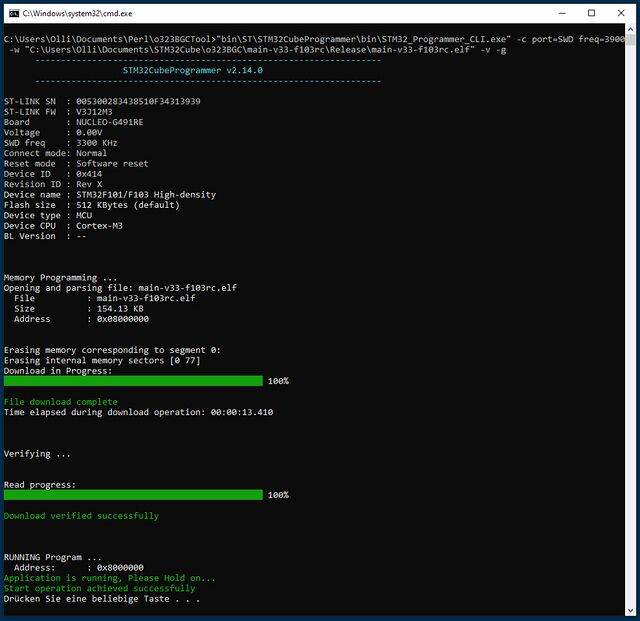
'''6.''' Now a black window (DOS console) should open and run the STM32CubeProgrammer flash program, as shown in the screenshot. Wait until it is finished (takes some seconds). The STorM32 board will be reset and start running. | |||
::[[File:Storm32-wiki-flash-firmware-swd-dosbox.jpg|640px]] | |||
Revision as of 18:25, 19 January 2024
This page is for instructions on how to flash firmware into v3.x and v4.x STorM32 boards.
For instructions on how to flash v1.3x STorM32 boards, please consult the article How to flash v1.x STorM32 boards.
For the v3.x/v4.x boards two situations can be distinguished:
- Upgrading: If your v3.x/v4.x board already runs a valid STorM32 firmware which you want to upgrade (or downgrade), then this is the recommended procedure to choose, since it is most simple. Go to Updating Firmware.
- First-time flashing: In all other cases, when your v3.x/v4.x board has not yet a STorM32 firmware installed or you don't want to use the upgrade method, this is what needs to be done. Go to First-Time Flashing.
Comment: The same distinction also exists for flashing NT modules, see How to flash NT Modules.
Updating Firmware
If your v3.x/v4.x STorM32 board runs already a firmware, then this is the canonical procedure for upgrading:
1. Connect the STorM32 board via its USB port to the PC.
- Comment: If this is the first time the board is connected via USB to the PC, then Win will immediately start with installing the appropriate USB driver. This takes quite a while (several minutes). Please, be patient and wait until Win reports that the device is ready for use. Do not interrupt the driver installation process before it is completed. Otherwise things can get messed up quite considerably, and installing the driver later can be a challenge.
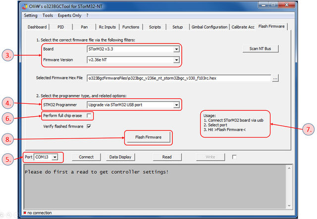
2. Run the GUI and go to the [GUI:Flash Firmware] tab (see the screenshot).
- Comment: In principle you can use any GUI version to flash any version of the firmware. However, a GUI which is of the same or higher version than the firmware which is to be installed provides easy access to the firmware via the selector fields on the [GUI:Flash Firmware] window.
3. In the combo boxes [Board] and [Firmware Version] select the correct board and desired firmware version.
- Comment: With these two selectors the correct firmware .hex file is chosen in the [Selected Firmware Hex File] field.
- Comment: It is important to choose the correct board version; otherwise you will flash a wrong firmware and the board will not functions correctly.
4. In the [STM32 Programmer] field select "Upgrade via STorM32 USB port".
5. In the [Port] field select the COM port which your STorM32 board is connected to (it's the same port you choose when connecting to the GUI).
- Comment: If you are not sure which the correct COM port is, then disconnect the STorM32 board from the PC, inspect the drop-down list and memorize the available COM ports, reconnect the STorM32 board and wait until it is enumerated by Win, inspect the drop-down list again, and chose the newly added COM port.
6. If required or desired check the [Perform full chip erase] check button.
7. Remind you about the upgrading process by reading the usage information.
8. Finally, hit the [Flash Firmware] button.
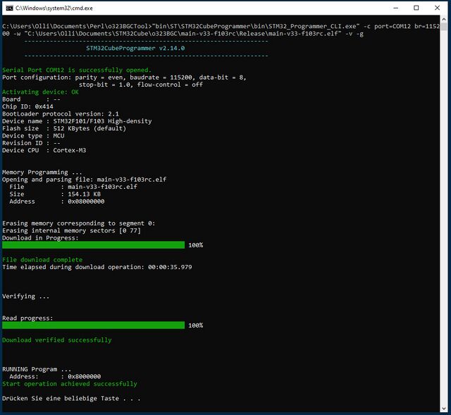
9. Now a black window (DOS console) should open and run the STM32CubeProgrammer flash program, as shown in the screenshot. Wait until it is finished (takes some seconds). The STorM32 board will be reset and start running.
Trouble Shooting
- The STorM32 board has no power: Connect the board to the computer via USB to power it.
- Wrong serial port is selected in the tool.
- The black DOS box does not show up: Typically this happens because the firmware .zip file was not extracted.
- The black DOS box shows up, displaying a [OK] and [KO] together with an error message "No response from target, the bootloader cannot be started": The error message is correct, the bootloader could not be started, because e.g. a wrong COM port was selected, the STorM32 board wasn't put into bootloader mode, the connections are incorrect, and so on.
- The above steps run and the black DOS box shows the first two [OK] messages, but the downloading and verifying message lines are not be present and a firmware is not flashed: Go to Removing Read&Write Protections.
- The verify fails: First double-check that you are not using an outdated GUI version. Otherwise, click the [Perform full chip erase] check button and repeat. Note: This will also erase any setting; if needed save the settings to a file beforehand using the option in the "Setting" menu.
- The USB is not working: Please double-check that you've selected the correct board version in the [STorM32-BGC board] field.
- In case of troubles with the USB driver, consult the FAQ: Which drivers are needed for the USB?.
- On Win XP flashing via the GUI using the USB-TTL adapter will fail. See the section Flashing Procedure for Win XP.
- In order to test if the USB-TTL adapter is working properly, one can connect its Rx and Tx pins with each other, and use a terminal program, such as HTerm. When you send characters they should be immediately received.
First-Time Flashing
If your v3.x/v4.x STorM32 board has not yet been flashed with a STorM32 firmware, or runs a different firmware, then one needs to resort to grass roots flashing methods for flashing the firmware (first-time flashing).
In general, the STM32 micro-controllers which are used in the STorM32 boards provide two different built-in methods for flashing firmware:
- via the serial system bootloader using a USB-TTL adapter
- via SWD using a ST-Link programmer
For v3.x/v4.x boards method 1. is relatively convenient, since these boards have the USB-TTL adapter integrated and thus no additional hardware is needed for doing this. However, the grain of salt is that the BOOT0 pin needs to be temporarily shortened to GND by closing the solder jumper.
Method 2. requires a dedicated ST-Link programmer device. These are cheaply available, but nevertheless it is an additional piece of hardware, which one needs.
Flashing via System Bootloader
1. Important: Find the BOOT0 solder jumper on the STorM32 board, and close it with a drop of solder.
2. Connect the STorM32 board via the USB plug to the PC (it is important to do that after step 1, alternatively you can reset/repower the board).
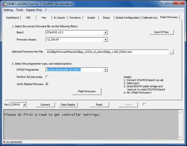
3. Run the GUI and go to the [GUI:Flash Firmware] tab and choose your settings:
- In the combo boxes [Board] and [Firmware Version] select the correct board and desired firmware version.
- In the [STM32 Programmer] field Select "System Bootloader @ UART1".
- In the [Port] field select the COM port which your STorM32 board is connected to.
4. Finally, hit the [Flash Firmware] button.
5. Now a black window (DOS console) should open and run the STM32CubeProgrammer flash program, as shown in the above. Wait until it is finished (takes some seconds).
6. Important: Do not forget to open the BOOT0 solder jumper.
Flashing via SWD
1. You need a STLink/V2 programmer. To buy one just search for e.g. "STlink" on ebay, aliexpress, etc. They look something like this:
2. Connect the SWD pins from the STorM32 board to the pins of your ST-Link programmer. The SWD pins on the v3.3 board are near the USB plug, anf on the v4.1 board near the LEDs.
- "SWDIO" to "SWDIO"
- "SWCLK" to "SWCLK"
- "GND" to "GND"
3. Power up your STorM32 over USB, and connect your ST-Link programmer over USB to a PC.
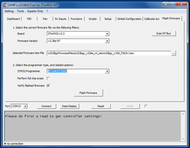
4. In the GUI go to the [GUI:Flash Firmware] tab and choose your settings. It should look something like this:
5. Push the [Flash Firmware] button.
6. Now a black window (DOS console) should open and run the STM32CubeProgrammer flash program, as shown in the screenshot. Wait until it is finished (takes some seconds). The STorM32 board will be reset and start running.
