How to flash v1.x STorM32 boards: Difference between revisions
No edit summary |
|||
| (10 intermediate revisions by the same user not shown) | |||
| Line 1: | Line 1: | ||
The following describes the process of flashing firmware onto {{WARNING|''''' | The following describes the process of flashing firmware onto {{WARNING|'''''v1.3/v1.3x'''''}} STorM32 boards. | ||
For instructions on how to flash '''''v3.x''''' STorM32 boards, please consult the article [[How to flash firmware]]. | For instructions on how to flash {{WARNING|'''''v3.x'''''}} STorM32 boards, please consult the article [[How to flash firmware]]. | ||
__TOC__ | __TOC__ | ||
| Line 7: | Line 7: | ||
== Flashing Firmware using a USB-TTL Adapter == | == Flashing Firmware using a USB-TTL Adapter == | ||
The following steps describe the recommended procedure for flashing v1.3x STorM32 boards: | |||
''' | '''1.''' You need a standard USB-TTL adapter (CP2102, FTDI, CH340, {{WARNING|'''''not'''''}} PL2303, see [[STorM32_FAQ#Which USB-TTL adapter should I use.3F|FAQ: Which USB-TTL adapter should I use?]]). Get your USB-TTL adapter to work by installing all Windows drivers as requested by the vendor (usually it should be auto-installed by Win, and you should not have to bother with this step). | ||
::[[File:Usb-to-uart-driver.png|360px]] | |||
'''2.''' Unplug (!) the USB-TTL adapter. | |||
'''3.''' You don't have to worry if it is a 5 V adapter or not, the pins on the STorM32 board we are going to connect the adapter to are 5 V tolerant. | |||
:RC-1 = Uart1-Tx -> connect it to Rx of the USB-TTL adapter | '''4.''' Connect the USB-TTL adapter to the STorM32 board at the pins labeled RC (!), as shown in the schemes. The firmware is '''''not''''' programmed via the UART port, '''''not''''' via the USB port, but via the RC pins: | ||
* RC-GND = GND -> connect it to GND of the USB-TTL adapter | |||
* RC-0 = Uart1-Rx -> connect it to Tx of the USB-TTL adapter | |||
* RC-1 = Uart1-Tx -> connect it to Rx of the USB-TTL adapter | |||
{{COMMENT|Neither a 5 V nor a 3.3 V nor any other power pin on the USB-TTL adapter is used... only three wires running from adapter to board.}} | |||
::[[File:Stom32-bgc-flashing-w-usbttladapter-connections-02.jpg|640px]] | |||
'''5.''' Connect the STorM32 board via USB to the computer. We are not using this connection yet, but we power the board via USB.<br/> | |||
{{WARNING|If the board has already a firmware installed and this is the first-time connection to your PC, then Windows will install the USB driver for the STorM32 board. This can take quite some time (several minutes). Please, be patient and wait until Win reports that the device is ready for use. Do '''''not''''' interrupt the install process.}} | |||
''' | '''6.''' Download the newest firmware, unzip it and run the GUI, in this example the o323BGCTool_v222e.exe program. It does not matter what the currently installed firmware is; you use the GUI that comes with the firmware zip file. Get the zip file from here: [[Downloads]]. | ||
{{ | '''7.''' In the GUI select the {{GUI|Flash Firmware}} tab on the very right hand side and select the hardware revision of your board in the {{GUIFIELD|Board}} combo box (if your revision is not listed, choose the closest one). This does change the firmware file, which is going to be used, in the text field {{GUIFIELD|Selected Firmware Hex File}} below. Double-check that the latest firmware version is selected in the {{GUIFIELD|Firmware Version}} field. | ||
''' | {{COMMENT|It is '''important''' to choose the correct board version; otherwise the board will not functions correctly.}} | ||
<!--::[[File:Storm32-wiki-flash-firmware-v1x.jpg|640px]]--> | |||
::[[File:Storm32-bgc-firmware-board.jpg|360pxpx]] | |||
'''8.''' Double-check that in the field {{GUIFIELD|STM32 Programmer}} the option {{GUIPARAM|System Bootloader @ UART1}} is selected. | |||
::[[File:Storm32-bgc-firmware-programmer.jpg|360pxpx]] | |||
'''9.''' Now select the COM port of the USB-TTL adapter ('''''not''''' the STorM32 board, but the USB-TTL adapter). This is done with the {{GUIFIELD|Com Port}} selector in the middle of the screen, '''''not''''' with the {{GUIFIELD|Port}} selector in the bottom left! Click on the drop down box to see all currently available COM ports. Since we have not yet connected the USB-TTL adapter to the computer, the new COM port which appears when plugging in the USB-TTL adapter will be the one to use. Hence remember that list of ports to identify the new one in the next step. | |||
::[[File:Storm32-bgc-firmware-comportA.jpg|360px]] | |||
''' | '''10.''' Plug in the USB-TTL adapter and click again on the {{GUIFIELD|Com Port}} selector to see the updated list of available COM ports. Select the new one. | ||
::[[File:Storm32-bgc-firmware-comportB.jpg|360px]] | |||
''' | '''11.''' The v1.3x boards have two buttons, the boot and reset button. When the board is started, the very first thing the microcontroller is doing is to check if the boot button is momentarily pressed. If it is, then the bootloader mode is entered, else normal operation starts. The best way of entering the bootloader mode is to press the boot button and while it is pressed to press and release the reset button to initiate a hard reset. | ||
::[[File:Firmware-bootloadermode.jpg|320px]] | |||
::[[File:Storm32-wiki-flash-firmware-key-sequence-01.jpg|640px]] | |||
'''12.''' Check if the board is in bootloader mode: The board should appear to be "dead", i.e., both the green and red LEDs should be off (the yellow LED is irrelevant). If the green and red LEDs are blinking, then it is in normal operation and the bootloader mode has not been entered correctly, e.g., because the boot button was not pressed while the reset button was released. | |||
::[[File:Firmware-bootloadermode-leds.jpg|320px]] | |||
'''13.''' Now the board is listening on the RC pins for data, the USB-TTL adapter is connected, and the correct COM port of the adapter is selected, so you finally can click the {{GUIFIELD|Flash Firmware}} button. | |||
::[[File:Storm32-bgc-firmware-flash.jpg|360px]] | |||
'''14.''' Now a black DOS box will open and a sequence of downloading and verifying the firmware is shown, if everything is OK.<br/> | |||
{{WARNING|If the board has already a firmware installed and this is the first-time connection to your PC, then Windows will install the USB driver for the STorM32 board. This can take quite some time (several minutes). Please, be patient and wait until Win reports that the device is ready for use. Do '''''not''''' interrupt the install process.}} | |||
::[[File: | {{COMMENT|If you want to understand better what the print outs in the DOS box mean, you may read [[https://www.rcgroups.com/forums/showpost.php?p=38338505&postcount=10343]].}} | ||
{{COMMENT|Since firmware version v2.67e STM32CubeProgrammer is used instead of FlashLoader and the print out in the DOS box looks differently than shown here.}} | |||
::[[File:flash.png|360px]] | |||
''' | '''15.''' After the flashing is completed, the STorM32 board is reset and will start running. It is now fully operational and you may disconnect the USB-TTL adapter. | ||
:: | The flashing process is also nicely described in this video by rcgroups user alcurtis93: | ||
::{{#ev:youtube|HwaHjRw1Qqg|480}} | |||
==== Trouble Shooting ==== | |||
* The board has no power: Connect the board to the computer via USB to power it. | |||
* The pins labeled UART are used for flashing: This is wrong, the RC pins must be used. | |||
* Wrong serial port is selected in the tool. | |||
* The black DOS box does not show up: Typically this happens because the firmware .zip file was not extracted. | |||
* The black DOS box shows up, displaying a [OK] and [KO] together with an error message "No response from target, the bootloader cannot be started": The error message is correct, the bootloader couldn't be started, because e.g. a wrong COM port was selected, the STorM32 board wasn't put into bootloader mode, the connections are incorrect, and so on. | |||
* The above steps run and the black DOS box shows the first two [OK] messages, but the downloading and verifying message lines are not be present and a firmware is not flashed: Go to [[How to flash firmware#Removing Read&Write Protections|Removing Read&Write Protections]]. | |||
* The verify fails: First double-check that you are not using an outdated GUI version. Otherwise, click the {{GUIFIELD|Perform full chip erase}} check button and repeat. Note: This will also erase any setting; if needed save the settings to a file beforehand using the option in the "Setting" menu. | |||
* The USB is not working: Please double-check that you've selected the correct board version in the {{GUIFIELD|STorM32-BGC board}} field. | |||
* In case of troubles with the USB driver, consult the [[STorM32_FAQ#Which_drivers_are_needed_for_the_USB.3F|FAQ: Which drivers are needed for the USB?]]. | |||
* On Win XP flashing via the GUI using the USB-TTL adapter will fail. See the section [[#Flashing Procedure for Win XP|Flashing Procedure for Win XP]]. | |||
* In order to test if the USB-TTL adapter is working properly, one can connect its Rx and Tx pins with each other, and use a terminal program, such as HTerm. When you send characters they should be immediately received. | |||
* Check if the XOR chip is mounted on the board: [https://www.rcgroups.com/forums/showpost.php?p=49429219&postcount=13850 XOR chip on your board?], [https://www.rcgroups.com/forums/showpost.php?p=51759997&postcount=15061]. | |||
* Check if your board comes with a GD32F103 chip instead of a genuine STM32F103 chip: [https://www.rcgroups.com/forums/showpost.php?p=51759997&postcount=15061]. | |||
== Flashing Procedure for Win XP == | |||
'''1.''' Download and install the Flash Loader Demonstrator from [http://www.st.com/web/en/catalog/tools/PF257525]. | '''1.''' Download and install the Flash Loader Demonstrator from [http://www.st.com/web/en/catalog/tools/PF257525]. | ||
| Line 78: | Line 104: | ||
{{COMMENT|The USB-TTL adapter needs to be connected to the PC before the Flash Loader Demonstrator is started}}. | {{COMMENT|The USB-TTL adapter needs to be connected to the PC before the Flash Loader Demonstrator is started}}. | ||
::[[File:XPFirmware1.jpg]] | ::[[File:XPFirmware1.jpg|320px]] | ||
'''4.''' If you have connected the USB-TTL adapter correctly and pressed the buttons you should see a green light and it should say that the target is readable. Click next. | '''4.''' If you have connected the USB-TTL adapter correctly and pressed the buttons you should see a green light and it should say that the target is readable. Click next. | ||
::[[File:XPFirmware2.jpg]] | ::[[File:XPFirmware2.jpg|320px]] | ||
'''5.''' The target on the next page should be correct, otherwise you will have to choose the controller and click next. | '''5.''' The target on the next page should be correct, otherwise you will have to choose the controller and click next. | ||
::[[File:XPFirmware3.jpg]] | ::[[File:XPFirmware3.jpg|320px]] | ||
'''6.''' Browse to the correct firmware file and click next. The upgrade will start. | '''6.''' Browse to the correct firmware file and click next. The upgrade will start. | ||
::[[File:XPFirmware4.jpg]] | ::[[File:XPFirmware4.jpg|320px]] | ||
'''7.''' After the firmware is downloaded to the controller you must restart it and it is now ready for use. | '''7.''' After the firmware is downloaded to the controller you must restart it and it is now ready for use. | ||
::[[File:ready.jpg]] | ::[[File:ready.jpg|320px]] | ||
== Removing Read&Write Protections == | |||
Some boards are unfortunately shipped with a read/write protection on the flash. As a result, storing parameters permanently in the board and flashing new firmware will fail. To remove the protections do the following: | Some boards are unfortunately shipped with a read/write protection on the flash. As a result, storing parameters permanently in the board and flashing new firmware will fail. To remove the protections do the following: | ||
| Line 108: | Line 133: | ||
'''4.''' Go back to the [[#Flashing Firmware using a USB-TTL Adapter|Flashing Firmware using a USB-TTL Adapter]] section in the above and flash the firmware anew. | '''4.''' Go back to the [[#Flashing Firmware using a USB-TTL Adapter|Flashing Firmware using a USB-TTL Adapter]] section in the above and flash the firmware anew. | ||
== Flashing Firmware using a STLink/V2 (SWD) Programmer == | == Flashing Firmware using a STLink/V2 (SWD) Programmer == | ||
The procedure is identical to the one described in this article [[How_to_flash_firmware#Flashing_via_SWD | Flashing via SWD]], except that on the v1.3x STorM32 boards the SWD pins are located near the AUX ports. | |||
== Flashing the Micro STorM32 Board == | == Flashing the Micro STorM32 Board == | ||
Latest revision as of 12:15, 22 November 2023
The following describes the process of flashing firmware onto v1.3/v1.3x STorM32 boards.
For instructions on how to flash v3.x STorM32 boards, please consult the article How to flash firmware.
Flashing Firmware using a USB-TTL Adapter
The following steps describe the recommended procedure for flashing v1.3x STorM32 boards:
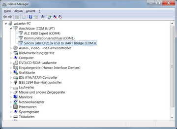
1. You need a standard USB-TTL adapter (CP2102, FTDI, CH340, not PL2303, see FAQ: Which USB-TTL adapter should I use?). Get your USB-TTL adapter to work by installing all Windows drivers as requested by the vendor (usually it should be auto-installed by Win, and you should not have to bother with this step).
2. Unplug (!) the USB-TTL adapter.
3. You don't have to worry if it is a 5 V adapter or not, the pins on the STorM32 board we are going to connect the adapter to are 5 V tolerant.
4. Connect the USB-TTL adapter to the STorM32 board at the pins labeled RC (!), as shown in the schemes. The firmware is not programmed via the UART port, not via the USB port, but via the RC pins:
- RC-GND = GND -> connect it to GND of the USB-TTL adapter
- RC-0 = Uart1-Rx -> connect it to Tx of the USB-TTL adapter
- RC-1 = Uart1-Tx -> connect it to Rx of the USB-TTL adapter
Comment: Neither a 5 V nor a 3.3 V nor any other power pin on the USB-TTL adapter is used... only three wires running from adapter to board.
5. Connect the STorM32 board via USB to the computer. We are not using this connection yet, but we power the board via USB.
If the board has already a firmware installed and this is the first-time connection to your PC, then Windows will install the USB driver for the STorM32 board. This can take quite some time (several minutes). Please, be patient and wait until Win reports that the device is ready for use. Do not interrupt the install process.
6. Download the newest firmware, unzip it and run the GUI, in this example the o323BGCTool_v222e.exe program. It does not matter what the currently installed firmware is; you use the GUI that comes with the firmware zip file. Get the zip file from here: Downloads.
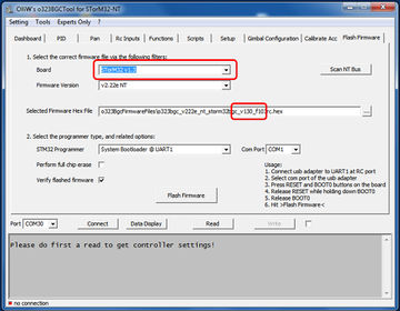
7. In the GUI select the [GUI:Flash Firmware] tab on the very right hand side and select the hardware revision of your board in the [Board] combo box (if your revision is not listed, choose the closest one). This does change the firmware file, which is going to be used, in the text field [Selected Firmware Hex File] below. Double-check that the latest firmware version is selected in the [Firmware Version] field.
Comment: It is important to choose the correct board version; otherwise the board will not functions correctly.
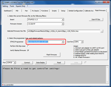
8. Double-check that in the field [STM32 Programmer] the option "System Bootloader @ UART1" is selected.
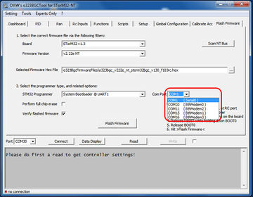
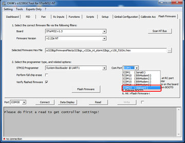
9. Now select the COM port of the USB-TTL adapter (not the STorM32 board, but the USB-TTL adapter). This is done with the [Com Port] selector in the middle of the screen, not with the [Port] selector in the bottom left! Click on the drop down box to see all currently available COM ports. Since we have not yet connected the USB-TTL adapter to the computer, the new COM port which appears when plugging in the USB-TTL adapter will be the one to use. Hence remember that list of ports to identify the new one in the next step.
10. Plug in the USB-TTL adapter and click again on the [Com Port] selector to see the updated list of available COM ports. Select the new one.
11. The v1.3x boards have two buttons, the boot and reset button. When the board is started, the very first thing the microcontroller is doing is to check if the boot button is momentarily pressed. If it is, then the bootloader mode is entered, else normal operation starts. The best way of entering the bootloader mode is to press the boot button and while it is pressed to press and release the reset button to initiate a hard reset.
12. Check if the board is in bootloader mode: The board should appear to be "dead", i.e., both the green and red LEDs should be off (the yellow LED is irrelevant). If the green and red LEDs are blinking, then it is in normal operation and the bootloader mode has not been entered correctly, e.g., because the boot button was not pressed while the reset button was released.
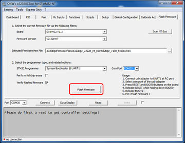
13. Now the board is listening on the RC pins for data, the USB-TTL adapter is connected, and the correct COM port of the adapter is selected, so you finally can click the [Flash Firmware] button.
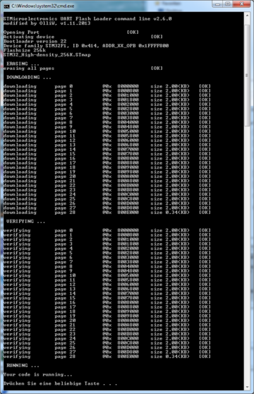
14. Now a black DOS box will open and a sequence of downloading and verifying the firmware is shown, if everything is OK.
If the board has already a firmware installed and this is the first-time connection to your PC, then Windows will install the USB driver for the STorM32 board. This can take quite some time (several minutes). Please, be patient and wait until Win reports that the device is ready for use. Do not interrupt the install process.
Comment: If you want to understand better what the print outs in the DOS box mean, you may read [[1]].
Comment: Since firmware version v2.67e STM32CubeProgrammer is used instead of FlashLoader and the print out in the DOS box looks differently than shown here.
15. After the flashing is completed, the STorM32 board is reset and will start running. It is now fully operational and you may disconnect the USB-TTL adapter.
The flashing process is also nicely described in this video by rcgroups user alcurtis93:
Trouble Shooting
- The board has no power: Connect the board to the computer via USB to power it.
- The pins labeled UART are used for flashing: This is wrong, the RC pins must be used.
- Wrong serial port is selected in the tool.
- The black DOS box does not show up: Typically this happens because the firmware .zip file was not extracted.
- The black DOS box shows up, displaying a [OK] and [KO] together with an error message "No response from target, the bootloader cannot be started": The error message is correct, the bootloader couldn't be started, because e.g. a wrong COM port was selected, the STorM32 board wasn't put into bootloader mode, the connections are incorrect, and so on.
- The above steps run and the black DOS box shows the first two [OK] messages, but the downloading and verifying message lines are not be present and a firmware is not flashed: Go to Removing Read&Write Protections.
- The verify fails: First double-check that you are not using an outdated GUI version. Otherwise, click the [Perform full chip erase] check button and repeat. Note: This will also erase any setting; if needed save the settings to a file beforehand using the option in the "Setting" menu.
- The USB is not working: Please double-check that you've selected the correct board version in the [STorM32-BGC board] field.
- In case of troubles with the USB driver, consult the FAQ: Which drivers are needed for the USB?.
- On Win XP flashing via the GUI using the USB-TTL adapter will fail. See the section Flashing Procedure for Win XP.
- In order to test if the USB-TTL adapter is working properly, one can connect its Rx and Tx pins with each other, and use a terminal program, such as HTerm. When you send characters they should be immediately received.
- Check if the XOR chip is mounted on the board: XOR chip on your board?, [2].
- Check if your board comes with a GD32F103 chip instead of a genuine STM32F103 chip: [3].
Flashing Procedure for Win XP
1. Download and install the Flash Loader Demonstrator from [4].
2. Do step 1 to 4 under Flashing Firmware using a USB-TTL Adapter.
3. Start the Flash Loader Demonstrator, choose the correct COM port and then press the Boot0 and Reset buttons on the controller as described in step 10 under Flashing Firmware using a USB-TTL Adapter. Click next.
Comment: The USB-TTL adapter needs to be connected to the PC before the Flash Loader Demonstrator is started.
4. If you have connected the USB-TTL adapter correctly and pressed the buttons you should see a green light and it should say that the target is readable. Click next.
5. The target on the next page should be correct, otherwise you will have to choose the controller and click next.
6. Browse to the correct firmware file and click next. The upgrade will start.
7. After the firmware is downloaded to the controller you must restart it and it is now ready for use.
Removing Read&Write Protections
Some boards are unfortunately shipped with a read/write protection on the flash. As a result, storing parameters permanently in the board and flashing new firmware will fail. To remove the protections do the following:
1. Follow steps 1-3 of Flashing Procedure for Win XP for downloading, installing and starting the Flash Loader Demonstrator of STMicroelectronics.
2. Do also step 4, you will now however see the message WARNING: When you click "Remove Protection" the flash will be mass erased and all data will be lost.. Click on Remove Protection. This will remove the protections, as well as fully erase the flash memory.
3. Close the Flash Loader Demonstrator after it has completed and restart the STorM32 board. The LEDs are not operational since also any firmware got erased in the previous step.
4. Go back to the Flashing Firmware using a USB-TTL Adapter section in the above and flash the firmware anew.
Flashing Firmware using a STLink/V2 (SWD) Programmer
The procedure is identical to the one described in this article Flashing via SWD, except that on the v1.3x STorM32 boards the SWD pins are located near the AUX ports.
Flashing the Micro STorM32 Board
The Micro STorM32 board doesn't provide BOOT0 and RESET buttons. Hence, flashing with a USB-TTL adapter is not easily possible. It can be done though: BOOT0 must be shortcut to 3.3 V by e.g. soldering a wire as shown in the picture below, and powering up the board to bring it into bootloader mode. For a more detailed description of the process please see also cro_flyer's post at rcg.
This board does however expose the SWD pins, and flash it using a ST-Link programmer is thus the easiest method. The connections are:
- "O" to "SWDIO"
- "K" to "SWCLK"
- "G" to "GND"
Where "O", "K" and "G" refer to labeled locations on the bottom side of the board that you must solder to.
