I recently shifted away from Atmel’s AVR micro controllers towards ST’s STM32 chips. These are really cool and I start to like them a lot, but there is much less information available on the web than for the AVR’s (I couldn’t even identify a good STM32 forum). In addition, even if available I often found the information to be not in a useful format. Hence, I decided to collect some of the bits and pieces on this page here.
So, this is not intended to be a tutorial; it’s rather a collection of info which I find relevant or useful, but are not usually found. The basic stuff such as setting up ports, timers, adcs, etc., is sufficiently treated in available tutorials (see last chapter below). No need to duplicate them; copy&pasting their example codes allows a quick start.
By the way, I’m using Windows. So, whenever it comes to platform specific things you know now what I’m referring to.
1. Development Boards
1.1. Blue Pill, 1.2. VL Discovery, 1.3. Goodluckbuy F103RC, 1.4. LC-Tech F103C8, 1.5. Maple Mini F103CB, 1.6. Olimex H103 F103RB
2. STM32 Microprocessor Details
2.1. F103T8, 2.2. F103CB, 2.3. F103RB, 2.4. F103RC/D/E
3. CooCox Toolchain
3.1. Installation, 3.2. Setting up a Project, 3.3. CoIDE Pitfalls
4. Code Snippets
5. STMFlashLoader
6. External Tutorials
1. Development Boards
In contrast to the Atmega-Arduino world, there is really a lack of nice and cheap STM32 boards. I would have loved to find anything like the Arduino Nano for STM32, and this for few bucks (yes, there is the Maple Mini, but…). Anyhow, here are my „best“ finds. The Olimex I normally would not have considered because of its price, but at that time the China Post somehow made troubles, and I got impatient… so, I bought one.
1.1. Blue Pill
This is probably THE board: It has everything one needs, the pins are labelled, it is small, and really SUPER cheap. The only drawback is maybe that the processor is just a F103C8, but it should be good for many purposes (and the F103C8 in fact also comes with 128k like the F103CB, see post #11 and following here). Good info on the board is available also here.
electronic scheme
STM32duino: Blue Pill Scheme
dimensions
53 x 22 mm2
hardware
STM32 F103 C8
8 MHz crystal + 32 kHz RTC crystal
port usage
PC13: LED
PA11 – USB-DM: USB D-
PA12 – USB-DP: USB D+
configurable features
The board provides 2 jumpers, to configure BOOT0, BOOT1.
1.2. STM32 VL Discovery
There are some different possibilities to flash STM32 chips, but as a beginner I didn’t wanted to fool around. So I decided to buy this development board, since it seems to be the cheapest way to get a ST-Link/V2. Resembling a lot the AVR’s ISP, the ST-Link/V2 approach felt very familiar to me and I hence opted for it. And indeed, I didn’t had any problems with it, it just worked. One only has to download and install the ST-Link utility and the appropriate USB driver from ST’s web page.
- ST’s STM32 VL Discovery web page
- STM32F100RB data sheet
- ST’s ST-LINK/V2 web page (scroll down to find everything you need)
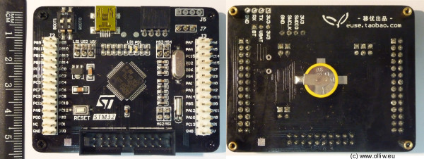
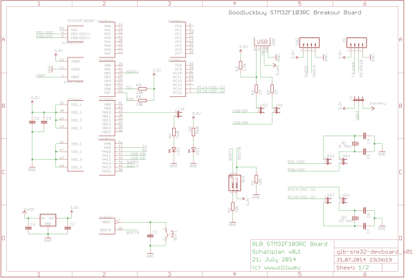
1.3. Goodluckbuy STM32F103RC breakout board
This is the only cheap development board with an F103RC prozessor I know about, and it isn’t too bad: It has everything on board what is needed (inclusive a 3 V battery) and the pins are labelled. It is however not really small, but it’s cheap.
- I bought it at GLB for $10.77 (incl. shipping) (link).
dimensions
69 x 55 mm2
hardware
STM32 F103 RC
8 MHz crystal + 32 kHz RTC cyrstal
port usage
All hardware features can be enabled/disabled individually via jumpers.
configurable features
Jumper MS3/MS4 – connects 8MHz crystal and capacitors to
Jumper MS1/MS2 – connects 32kHz crystal and capacitors to PC14/PC15
Jumper US1/US2 – connects USB D+ and USB D- to
Jumper LS1 – connects a LED to PB10
Jumper J7 – connects 3.3V or the battery to VBAT
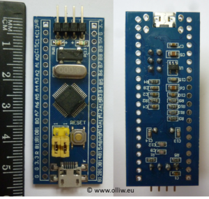
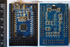
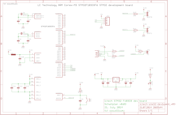
1.4. Shenzhen LC Technology STM32F103C8 development board
Very nice development board, I like it: It has everything on board, the pins are labelled, and it is relatively small and really cheap. The JTAG connector can be cut off, which makes the board really quite small. The only drawback is maybe that the processor is just a F103C8, but it should be good for many purposes (and the F103C8 in fact also comes with 128k like the F103CB, see post #11 and following here).
- Shenzhen LC Technology web page
- I bought it at ebay for $11.08 (e_goto), it is also available at BG for $5.68 ((link)), Aliexpress for $6.39 (link), GLB for $10.08 (link), DX for $12.63 (link), and several other sources – I’ve seen it even for below $5 (prices include shipping)
dimensions
52 x 36 mm2 (wo usb plug), weight 14.3 g
hardware
STM32 F103 C8
8 MHz crystal + 32 kHz RTC crystal
port usage
PA11 – USB-DM: USB D-
PA12 – USB-DP: USB D+
configurable features
Jumper P2 – connects 1.5k pullup resistor to USB D+
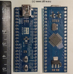
1.5. Maple Mini STM32F103CB development board
This is another board, which I like much: It offers everything needed, is by far the smallest board and available at a rediculously low price. It has a F103CB processor installed, which should be sufficient for many purposes.
- Leaflabs Maple Mini web page
- It is available in many places, e.g. from aliexpress, I’ve seen it for even as little as $2
electronic scheme
https://github.com/leaflabs/maplemini/blob/master/maplemini.pdf
dimensions
51.6 x 18.8 mm2 (wo usb plug), weight 4.2 g
hardware
STM32 F103 CB
8 MHz crystal
port usage
PA11 – USB-DM: USB D-
PA12 – USB-DP: USB D+
see also GPIO Information
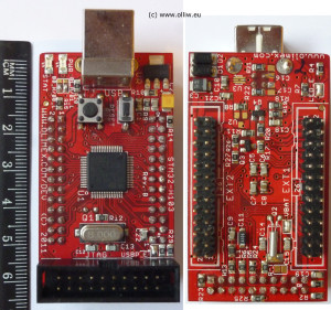
1.6. Olimex STM32-H103 STM32F103RB development board
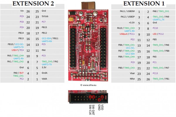
That’s a nice development board. But: It is not really cheap, it uses a big USB type B plug, and the pins are not labelled. The latter makes using the board cumbersome. I hence created a document with the pin layout, which I find indispensable; you’ll find it below.
electronic scheme
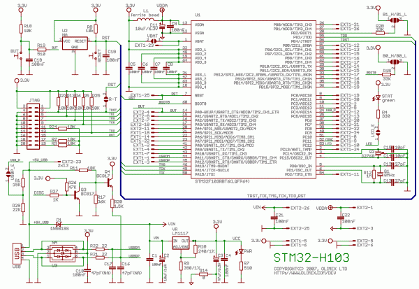 (by Olimex)
pin layout
dimensions
61 x 34 mm2
hardware
STM32 F103 RB
8 MHz crystal + 32 kHz RTC crystal
port usage
PA0 – BUT: connected via a rc network to a button
PC12 – LED: connected via a solder jumper to a led
PA11 – USB-DM: USB D-
PA12 – USB-DP: USB D+
PC11 – USB-DISC: connected to a transistor network to enable/pull down D+
PC4 – USB-P: connected via a solder jumper to a resistor voltage devide to detect USB power
configurable features
The board provides 6 solder jumpers, to configure BOOT0, BOOT1, the status LED, USB power, VBAT, and RESET.
2. STM32 Microprocessor Details
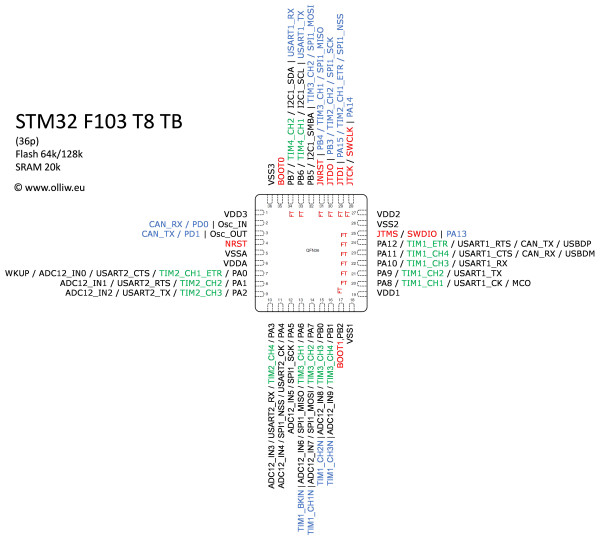
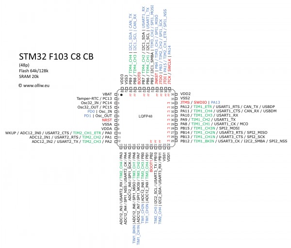
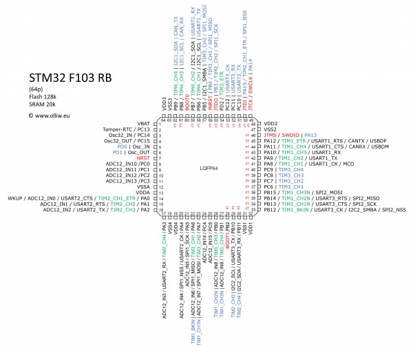
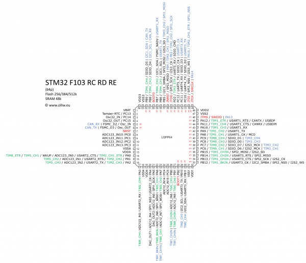
At the beginning I found the pin layouts quite confusing, in particular as the data sheets just provide a list of the pin functions, and because of the possibility to map some of the alternative functions to other pins. So I created some documentation, which I found more useful, and which I wouldn’t want to miss anymore, but see yourself.
Pin Properties
As regards the pins, I’d like to distinguish three categories: „special“ pins, 5V tolerant pins, and „normal“ pins.
To me, the special pins are those which are not available or usually would not be used as ports, i.e. power supply pins, oscillator pins, JTAG pins, BOOT pins, and so on. Some of the remaining GPIO pins are 5V tolerant, and indicated by a FT in the pictures below, while all the rest, the normal pins, are – well – just normal. Inspection shows:
Rule of thumb: Pins associated to the ADC are normal pins, while the other GPIO pins are 5V tolerant.
Exceptions exist, most notably pin PB5, which is not 5V tolerant.
If any of the special pins is used as a GPIO port, one should carefully study the data sheet, since often they behave somewhat differently, e.g. have a pull up enabled as default, and so on.
STM32 F103 T8
72 MHz, Flash 128k, SRAM 20k, 36 pins
medium density performance line
data sheet, reference manual, Cortex-M3 programming manual
STM32 F103 CB
72 MHz, Flash 128k, SRAM 20k, 48 pins
medium density performance line
data sheet, reference manual, Cortex-M3 programming manual
STM32 F103 RB
72 MHz, Flash 128k, SRAM 20k, 64 pins
medium density performance line
data sheet, reference manual, Cortex-M3 programming manual
STM32 F103 RC (RD RE)
72 MHz, Flash 256k, SRAM 48k, 64 pins
high density performance line
additional features: Tim8 (advanced), Tim5 (general), Tim6,7 (basic), Uart4,5, DAC
data sheet, reference manual, Cortex-M3 programming manual
3. CooCox Toolchain
Clearly, the STM32 world is not yet as easily accessible to hobbiests as the AVR world, but things become better, and this is to a large extend due to the CooCox project. The main part of CooCox is CoIDE, a fully integrated IDE based on arm-gcc and Eclipse.
I researched the other possibilities to set up a toolchain for STM32, but – for Windows users like me – they all look like a pain in the ass, and most of them are not free (or limited in possibilities). So, I am thankful to the CooCox project. The IDE has however its little flaws, but one gets used to them and working with the IDE goes smooth.
3.1. Installation
The installation of CooCox is fairly simple and fairly well described on the CooCox web page, and the two tutorials by Tech with Dave and Mikrocontroller listed in the tutorials chapter below. It’s obvious what to do: Download and install the ST-Link/V2 utility and USB driver, arm-gcc zip, and CoCenter. For the latter one has to register leaving an email address, but – well – that’s the price one has to pay for it. CoCenter allows to install all packages provided by CooCox; I did install only CoIDE, the other stuff is not needed (you can install them at any time later).
-
Get first your programmer running, for a ST-Link/V2 this means:
Go to the ST-LINK/V2 web page, scroll down and download the ST-LINK/V2 utility (STSW-LINK004) and required Windows USB driver (STSW-LINK003 or STSW-LINK006), unzip the .zip files (important!) and run the .exe files to install (just press always yes or next, and give it some time). There should be now a link to the program „STM32 ST-LINK Utility“ on your desktop. Note: You might be asked to restart the computer the first time you connect the ST-Link to it. So, it could be convenient to plug in (and out) the ST-Link now. - Go to the ARM-GCC web page and download the windows installer gcc-arm-none-eabi-xx-xxxxxx-xxxxxxxx-win32.exe, where the xx stand for the latest version number (e.g. 4_7-2013q3-20130916), and run the installer. On the last screen click the item „Add path to environment variable“, and then the „Finish“ button. During installation some windows pop up and close, but one cmd window will stay open at the end; you may close it.
- Go to the CoIDE web page, scroll down and click on „Download through CoCenter (Recommend)“, register, download, and run the .exe file to install. There should be now a link to the program „CoCenter“ on your desktop.
- Run CoCenter and first download and then install CoIDE. There should be now a link to the program „CoCenter“ on your desktop. Note: CoIDE doesn’t allow installation paths with e.g. blanks. Note2: CoCenter may terminate with a web browser error because of an incorrect web page link after a download; just rerun CoCenter and it will work. Note3: On one computer CoCenter terminated with a „CooCox Software Manager“ not working error, also downloading the CoIDE installer directly didn’t work, I couldn’t get things to work on this PC.
- Run CoIDE and set it up for the compiler as described on CooCox‘ Compiler Setting web page; for that just follow the screen shots by pressing the „Next >>“ button. Note: The tool chain path you have to select could read e.g. „C:\Program Files\GNU Tools ARM Embedded\4.7 2013q3\bin“, don’t get confused by the CooCox instructions, and don’t get confused by the fact that there is a „arm-none-eabi“ subfolder, it’s not the one you want to select.
- Go to CoIDE’s „Configuration“ tab, and double-check that in the „Options“ tab the „Adapter“ and „Port“ fields are set to ST-Link and SWD (if your programer is a ST-Link/V2).
3.2. Setting up a Project
CooCox provides a step-to-step description of how to set up a project (see the Quick Start web page), but I quickly „developed“ my own routine. The Quick Start tutorial is fine, but it doesn’t serve my needs. CooCox doesn’t memorize many of the „standard“ settings, so one has to go through every little bit and piece every time one creates a new project. Hopefully this will eventually improve.
- Go to the menu option „Project“->“New Project“, which opens the „New Project“ dialog window.
- Uncheck the item „Use default path“.
- Select the „Project Path“ and „Project Name“ entries, and press the „Next“ button (for my arrangement see below). Note: CoIDE doesn’t seem to „understand“ Windows; in the file browser dialog you don’t see the folders as shown in the explorer. In the browser, go to your user name, double click, and you should find your „My Documents“ folder.
- On the next screen move the mouse to the „Chip“ bubble, and press „Next“.
- On the next screen, scroll down to ST, double click, select the desired STM32 line, double click, select the desired STM32 chip, and double click. Press the „Finish“ button.
- Go now to the „Repository“ view, and select the required components. At minimum you need to click RCC (which automatically selects CMSIS core and CMSIS_Boot, which is all you need from the COMMON and BOOT areas), GPIO, and probably MISC (don’t confuse it with Misc). In the „Project“ view you can see how checking/unchecking a component in the „Repository“ view adds/removes the corresponding .c and .h files. Also a main.c is generated. I don’t use it and will remove it from the project.
These are the basic steps, but you most likely also want to do the next steps:
-
Go to the „Configuration“ view and there to „Compile“, and select Optimize Size (-Os) in the „Optimization“ field. The next time you do a build this will generate two errors, such as „… Error: registers may not be the same — `strexb r0,r0,[r1]'“. Go to the „Project“ view and open the file core_cm3.c, scroll down to the function indicated by the error, e.g. if the error says „strexb“ then find function
uint32_t __STREXB(uint8_t value, uint8_t *addr), and add a „&“ as shown here:
uint32_t __STREXB(uint8_t value, uint8_t *addr)

{

   uint32_t result=0;


   __ASM volatile ("strexb %0, %2, [%1]" : "=&r" (result) : "r" (addr), "r" (value) );

   return(result);

}
Repeat this for the other errors. This will correct the errors. Note: The CooCox team has repeatedly said that this has been corrected, but as of 17.Oct.2013 it is not. -
In the „Configuration“ view go to the „Compile“ tab, and enter „-std=gnu99;“ (wo the quotation marks) in the „Misc Controls“ field. This enables C99 programing things, such as
for(uint16_t i=0;i<1;i++){}. -
In the "Configuration" view go to the "Compile" tab, and enter "-lm;" (wo the quotation marks) in the "Misc Controls" field, and do the same in the "Link" tab. This enables using
#include <math.h>. -
The command to generate a .lss file is arm-none-eabi-objdump.exe -h -S %1.elf > %1.lss, where %1 is the output file name. One way to always get it, is to produce a file gcc2.lss.bat, with the content
@echo off

arm-none-eabi-objdump.exe -h -S %1.elf > %1.lss
and to place it in the tool chain path (see step 5.). Then, in CoIDE go to "Configuration"->"User"->"After Build/Rebuild" and enter "gcc2lss.bat ${output.path}\Debug\bin\${output.name}" in one of the run fields, and check it.
Comment: Some literature states that CooCox sets clocks incorrectly in standard situations, and that the function SystemInit() needs to be called in main(). Both points are NOT valid anymore (at least from CooCox 1.7.4 on, and F10x devices). CoIDE now assumes that for all STM32 devices, except of the connectivity line, an external 8 MHz crystal is used, and sets clocks accordingly (see system_stm32f10x.c). Also, CooCox's startup code calls first SystemInit() and then main(), which means that then main() starts the startup code has been executed (see startup_stm32f10x_md.c).
One nasty thing, at least then you're coming from AVR Studio, is that for each project quite many .c and .h files have to be handled. The CMSIS/SPL and other libraries are quite handy and make life easy - once they're set up - but they come with many files, and usually quite some of them have to be modified according to your specific needs. Now, the point is, most of my projects I want to run on different hardware, with e.g. different STM32 controllers, but for each of them one has to set up an individual project. So, in order to avoid that one has to copy all self-written files to each project folder, which would result in many duplicates and would make maintenance difficult, I create a folder with the project name, e.g. "HelloWorld", and then place the individual (sub)projects for each hardware in subfolders named e.g. "F103RB". Any additional (non-CMSIS/SPL) library files, such as the CPAL or USB-FS library files, are placed into folders at the same level (and not in a subfolder to e.g. "F103RB"). My steps are as follows:
-
Do steps 1. to 5. as described before, but in step 2. chose the entries
Project Name: HelloWorld-F103RB
Project Path: ...\Documents\STM32\HelloWorld\F103RB
Here the folder "STM32" is the major folder in which I hold all STM32 projects. - In CoIDE I remove "main.c" from the project (I don't find it smart to have thousand files with the same name but different content on the computer).
- Using windows explorer I create a file "helloworld.c", which holds the main() function, and place it in the folder "HelloWorld". I also create folders for the other libraries, e.g. for CPAL the folder "STM32_CPAL_Driver", and copy the library files into them.
- In CoIDE's "Project" view I create a group "STM32_CPAL_Driver", and add the library files.
- In CoIDE's "Project" view I add the file "helloworld.c" as well as all other self-written files needed for the project.
- I usually do but should not forget the above steps 6. and 7.
In order to create a subproject for another chip, e.g. the F103C8, one would repeat these steps. However, the project name and folder would e.g. be "HelloWorld-F103C8" and "...\STM32\HelloWorld\F103C8", and one would not have to copy the additional library files and self-written files gain (one though has to add them to the project in CoIDE). Hence, there are now individual projects hold in the respective subfolders, but they all use the same self-written files. So far that's the best structure I could come up with.
3.3. CoIDE Pitfalls
under construction...
4. Code Snippets
under construction...
5. STMFlashLoader
The ST/Link works perfectly, but for some projects it would be more convennient to use the system bootloader accessible via UART1, which is factory-installed in every STM32 device (AN2606). It is just more likely that folks have a USB-TTL adapter flying around somewhere, and moreover a USB-TTL adapter is deadly cheap, and a versatile unit anyhow.
Fortunately, the protocol used by the system bootloader is well documented (AN3155) and ST provides the GUI program Flash Bootloader Demonstrator, useful .dll files, and a command-line interface (CLI) STMFlashLoader.exe. The GUI works fine, and its usage is well documented (UM0462 and google). It is not fancy, but it works.
The CLI program STMFlashLoader.exe deserves, however, some comments. A CLI program is useful in many instances, e.g. batch applications, and it seems that, being unhappy with ST's CLI program, several folks have written their own (e.g. afrodevices, stm32flash, stm32loader, Sloadhost.exe). I first tried STMFlashLoader, and didn't got it working, and so I tried two of the alternatives but didn't got happy with them either. Thus I went back to STMFlashLoader, and eventually realized that one has to specify a map file using the -i command. A working command line for, e.g. the VL Discovery, could be
"path/stmflashloader.exe" -c --pn 3 --br 115200 -i stm32_med-density-value_128k.STmap -e --all -d --fn "test.hex" --v -r --a 8000000
I found it strange that the CLI needs a map file to be explicitely given, since the GUI doesn't, it can somehow determine that itself. In addition I found this quite inconvennient, so I tried to figure out how things work. Unfortunately the source code of the GUI is not available, hence some research was required. Fortunately, the sources of the .dll files are available, which uncovered a usefull function to determine the flash size, and one of the configuration files yielded the memory addresses in which the flash size can be found. Et voila, things worked. It is also quite inconnvenient that the original CLI doesn't provide an option like the "erase required pages" of the GUI. So, this too was added.
Below you find the modified flash loader, called STMFlashLoaderOlliW.exe, and the source in a .zip. It provides the additional option -ow, which can be used instead of -i and aims at determining all required device dependent information automatically, as well as a parameter --ep, which erases the required pages before a flash. A working command line would be
"path/stmflashloaderolliw.exe" -c --pn 3 --br 115200 -ow -d --fn "test.hex" --ep --v -r --a 8000000
On this occasion I also made the output a bit more informative, and corrected the "Press any key" function.
A note: I of course don't own every STM32 device and hence could not test the code for all cases. I followed the documentation, and for the "typical" STM32 devices it should work, but as I said...
Download: STMFlashLoaderOlliW [.zip] (3.8 MB)
Usefull documents
- AN2606: STM32™ microcontroller system memory boot mode
- AN3155: USART protocol used in the STM32™ bootloader
- STSW-MCU005: Flash Bootloader Demonstrator
- UM0462: STM32™ and STM8™ Flash loader demonstrator
6. External Tutorials
As said before, there is by far not as much info available on the web as for the AVR's, but some tutorials exist, and some of them I found indeed helpful to get started.
-
STM32 article on www.mikrocontroller.net
(not totally up-to-date but nevertheless the first place to go) -
STM32 Tutorial by Diller Technologies
(my major source at the beginning, THANKS Diller!) -
Hello World tutorial for STM32 Discovery boards using CooCox CoIDE and GCC ARM by Tech with Dave
(listed because of its useful installation description of armgcc, CoIDe and ST-Link) -
Installation der Toolchain und erstes Projekt vonby Mikrocontroller
(another good description of the toolchain installation, together with the previous link things work out smoothly) - ARM Cortex Tutorials by embedds.com
- STM32 Clock Configuration by OliverBehr.de
-
Discovering the STM32 Microcontroller by Geoffrey Brown
(this is actually a book, useful, but not as useful as one might wish since the examples are quite specific)

19 Kommentare